Difference between revisions of "Repetrel"
(→Light) |
(→Debug) |
||
| (32 intermediate revisions by the same user not shown) | |||
| Line 10: | Line 10: | ||
== Versions == | == Versions == | ||
Repetrel version 5.x should be available in summer 2021. | |||
Repetrel version 4.x was first released in August 2019; the final 4.x release should be available in spring 2020. | |||
Repetrel version 3. | Repetrel version 3.x was first released in November 2017; the final 3.x release is from March 2019. | ||
Repetrel version | Repetrel version 2.x was first released in July 2015; the final 2.x release is from July 2016. | ||
Repetrel version | Repetrel version 1.x was first released in July 2014; the final 1.x release is from September 2014. | ||
Repetrel version A33 was released in 2013. | Repetrel version A33 was released in 2013. | ||
| Line 38: | Line 26: | ||
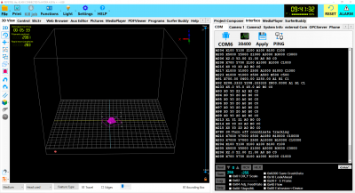
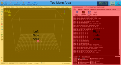
The Repetrel interface is divided into three main sections: the [[#Top Menu Area|Top Menu Area]], the [[#Left Side Area|Left Side Area]], and the [[#Right Side Area|Right Side Area]]: | The Repetrel interface is divided into three main sections: the [[#Top Menu Area|Top Menu Area]], the [[#Left Side Area|Left Side Area]], and the [[#Right Side Area|Right Side Area]]: | ||
[[File:Rep_ov.png]] [[File:Rep_ov2.png]] | [[File:Rep_ov.png|400px]] | ||
[[File:Rep_ov2.png|400px]] | |||
These are explained in detail in the subsequent sections: | These are explained in detail in the subsequent sections: | ||
| Line 50: | Line 39: | ||
==== File ==== | ==== File ==== | ||
[[File:Rep_file.png]] | [[File:Rep_file.png|200px]] | ||
The '''File''' menu (shown to the right) has the following options: | The '''File''' menu (shown to the right) has the following options: | ||
| Line 67: | Line 56: | ||
*'''Export''' will export the STL file(s) and save them to disk. | *'''Export''' will export the STL file(s) and save them to disk. | ||
*'''Zip and Send To USB''' has the following submenu options - all written to the first USB drive detected: | *'''Zip and Send To USB''' has the following submenu options - all written to the first USB drive detected: | ||
**'''REPETREL''' will | **'''REPETREL''' will create a .rar file of your entire C:\Repetrel directory. | ||
**'''REPETREL\BIN''' will create a .rar file of your C:\Repetrel\bin directory. | |||
**'''SLIC3R''' wil make a .rar file of your slic3r program folder. | **'''SLIC3R''' wil make a .rar file of your slic3r program folder. | ||
**'''Slic3r Recipes''' will make separate .rar files of your Printer, Print, and Filament recipe diretories. | **'''Slic3r Recipes''' will make separate .rar files of your Printer, Print, and Filament recipe diretories. | ||
| Line 74: | Line 64: | ||
**'''Screen Shot To Project Folder''' will currently do nothing (v4.001_A). | **'''Screen Shot To Project Folder''' will currently do nothing (v4.001_A). | ||
**'''Project GCODE''' will only work if you've opened a "Job" file. | **'''Project GCODE''' will only work if you've opened a "Job" file. | ||
I'''Prusa Recipes''' will export your Prusa recipes. | |||
*'''Email''' has the following submenu options; they only work if you've configured Repetrel with your email credentials. | *'''Email''' has the following submenu options; they only work if you've configured Repetrel with your email credentials. | ||
**'''Slic3r Settings''' | **'''Slic3r Settings''' | ||
| Line 90: | Line 81: | ||
*'''Update Firmware''' has the following submenu options: | *'''Update Firmware''' has the following submenu options: | ||
**'''HotHead Controller''' will launch the application to flash new firmware on your 103 hothead/hotbed controllers. | **'''HotHead Controller''' will launch the application to flash new firmware on your 103 hothead/hotbed controllers. | ||
**'''407 Motion Controller''' will launch the application to flash new firmware on your 407 motion controller. | **'''407 Motion Controller''' will launch the application to flash new firmware on your 407 or 429 motion controller. | ||
*'''Open Media File''' will open whatever media file you select. | |||
*'''Exit''' will close and exit the Repetrel program. | *'''Exit''' will close and exit the Repetrel program. | ||
*'''open media file''' will open a folder browser to open .wmv files. | *'''open media file''' will open a folder browser to open .wmv files. | ||
| Line 96: | Line 88: | ||
==== Print ==== | ==== Print ==== | ||
The '''Print''' button will cause the printer to commence executing the | The '''Print''' button will cause the printer to commence executing the files in your tree view that represent actions (GCODEs, converted DXFs, etc.). | ||
==== Kill job ==== | ==== Kill job ==== | ||
The '''Kill job''' button will cause the printer to cancel | The '''Kill job''' button will cause the printer to cancel whatever job is currently running. | ||
==== Functions ==== | ==== Functions ==== | ||
[[File:Rep_funct.png|right]] | [[File:Rep_funct.png|200px|right]] | ||
The '''Functions''' menu (shown to the right) has the following options: | The '''Functions''' menu (shown to the right) has the following options: | ||
| Line 123: | Line 115: | ||
==== Light ==== | ==== Light ==== | ||
[[File:Rep_light.png|right]] | [[File:Rep_light.png|200px|right]] | ||
The '''Light''' menu (shown to the right) has the following options for the X-Arm (ESR, EHR, 30M) or Gantry (Hydra 16A) printers. Please note that not all of these features (or axes) are available on all models: | The '''Light''' menu (shown to the right) has the following options for the X-Arm (ESR, EHR, 30M) or Gantry (Hydra 16A) printers. Please note that not all of these features (or axes) are available on all models: | ||
| Line 129: | Line 121: | ||
*'''Light On''' will send an '''M672 S01''' command, turning on the light. | *'''Light On''' will send an '''M672 S01''' command, turning on the light. | ||
*'''Light Off''' will send an '''M670 S00''' command, turning off the light. | *'''Light Off''' will send an '''M670 S00''' command, turning off the light. | ||
*'''X Home''' will send an '''M672 S10''' command, so the light toggles when the X Home sensor is tripped. It '''ALSO''' has a sub-menu: | *'''X Home''' will send an '''M672 S10''' command, so the light toggles when the X axis Home sensor is tripped. It '''ALSO''' has a sub-menu: | ||
**'''X Limit1''' will send an '''M670 S11''' command, so the light toggles when the X Limit1 is reached. | **'''X Limit1''' will send an '''M670 S11''' command, so the light toggles when the X axis Limit1 is reached. | ||
**'''X Limit2''' will send an '''M670 S12''' command, so the light toggles when the X Limit2 is reached. | **'''X Limit2''' will send an '''M670 S12''' command, so the light toggles when the X axis Limit2 is reached. | ||
**'''X STALL''' will send an '''M670 S13''' command, so the light toggles when the X motion is stalled. | **'''X STALL''' will send an '''M670 S13''' command, so the light toggles when the X motion is stalled. | ||
**'''X Drv Err''' will send an '''M670 S14''' command, so the light toggles when the X driver has an error. | **'''X Drv Err''' will send an '''M670 S14''' command, so the light toggles when the X driver has an error. | ||
*'''Y Home''' will send an '''M672 S20''' command, so the light toggles when the Y Home sensor is tripped. It '''ALSO''' has a sub-menu: | *'''Y Home''' will send an '''M672 S20''' command, so the light toggles when the Y axis Home sensor is tripped. It '''ALSO''' has a sub-menu: | ||
**'''Y Limit1''' will send an '''M670 S21''' command, so the light toggles when the Y Limit1 is reached. | **'''Y Limit1''' will send an '''M670 S21''' command, so the light toggles when the Y axis Limit1 is reached. | ||
**'''Y Limit2''' will send an '''M670 S22''' command, so the light toggles when the Y Limit2 is reached. | **'''Y Limit2''' will send an '''M670 S22''' command, so the light toggles when the Y axis Limit2 is reached. | ||
**'''Y STALL''' will send an '''M670 S23''' command, so the light toggles when the Y motion is stalled. | **'''Y STALL''' will send an '''M670 S23''' command, so the light toggles when the Y motion is stalled. | ||
**'''Y Drv Err''' will send an '''M670 S24''' command, so the light toggles when the Y driver has an error. | **'''Y Drv Err''' will send an '''M670 S24''' command, so the light toggles when the Y driver has an error. | ||
*'''Z Home''' will send an '''M672 S30''' command, so the light toggles when the Z Home sensor is tripped. It '''ALSO''' has a sub-menu: | *'''Z Home''' will send an '''M672 S30''' command, so the light toggles when the Z axis Home sensor is tripped. It '''ALSO''' has a sub-menu: | ||
**'''Z Limit1''' will send an '''M670 S31''' command, so the light toggles when the Z Limit1 is reached. | **'''Z Limit1''' will send an '''M670 S31''' command, so the light toggles when the Z axis Limit1 is reached. | ||
**'''Z Limit2''' will send an '''M670 S32''' command, so the light toggles when the Z Limit2 is reached. | **'''Z Limit2''' will send an '''M670 S32''' command, so the light toggles when the Z axis Limit2 is reached. | ||
**'''Z STALL''' will send an '''M670 S33''' command, so the light toggles when the Z motion is stalled. | **'''Z STALL''' will send an '''M670 S33''' command, so the light toggles when the Z motion is stalled. | ||
**'''Z Drv Err''' will send an '''M670 S34''' command, so the light toggles when the Z driver has an error. | **'''Z Drv Err''' will send an '''M670 S34''' command, so the light toggles when the Z driver has an error. | ||
*'''A Home''' will send an '''M672 S40''' command, so the light toggles when the A Home sensor is tripped. It '''ALSO''' has a sub-menu: | *'''A Home''' will send an '''M672 S40''' command, so the light toggles when the A axis Home sensor is tripped. It '''ALSO''' has a sub-menu: | ||
**'''A Limit1''' will send an '''M670 S41''' command, so the light toggles when the A Limit1 is reached. | **'''A Limit1''' will send an '''M670 S41''' command, so the light toggles when the A axis Limit1 is reached. | ||
**'''A Limit2''' will send an '''M670 S42''' command, so the light toggles when the A Limit2 is reached. | **'''A Limit2''' will send an '''M670 S42''' command, so the light toggles when the A axis Limit2 is reached. | ||
**'''A STALL''' will send an '''M670 S43''' command, so the light toggles when the A motion is stalled. | **'''A STALL''' will send an '''M670 S43''' command, so the light toggles when the A motion is stalled. | ||
**'''A Drv Err''' will send an '''M670 S44''' command, so the light toggles when the A driver has an error. | **'''A Drv Err''' will send an '''M670 S44''' command, so the light toggles when the A driver has an error. | ||
*'''B Home''' will send an '''M672 S50''' command, so the light toggles when the B Home sensor is tripped. It '''BLSO''' has a sub-menu: | *'''B Home''' will send an '''M672 S50''' command, so the light toggles when the B axis Home sensor is tripped. It '''BLSO''' has a sub-menu: | ||
**'''B Limit1''' will send an '''M670 S51''' command, so the light toggles when the B Limit1 is reached. | **'''B Limit1''' will send an '''M670 S51''' command, so the light toggles when the B axis Limit1 is reached. | ||
**'''B Limit2''' will send an '''M670 S52''' command, so the light toggles when the B Limit2 is reached. | **'''B Limit2''' will send an '''M670 S52''' command, so the light toggles when the B axis Limit2 is reached. | ||
**'''B STALL''' will send an '''M670 S53''' command, so the light toggles when the B motion is stalled. | **'''B STALL''' will send an '''M670 S53''' command, so the light toggles when the B motion is stalled. | ||
**'''B Drv Err''' will send an '''M670 S54''' command, so the light toggles when the B driver has an error. | **'''B Drv Err''' will send an '''M670 S54''' command, so the light toggles when the B driver has an error. | ||
*'''C Home''' will send an '''M672 S60''' command, so the light toggles when the C Home sensor is tripped. It '''ALSO''' has a sub-menu: | *'''C Home''' will send an '''M672 S60''' command, so the light toggles when the C axis Home sensor is tripped. It '''ALSO''' has a sub-menu: | ||
**'''C Limit1''' will send an '''M670 S61''' command, so the light toggles when the C Limit1 is reached. | **'''C Limit1''' will send an '''M670 S61''' command, so the light toggles when the C axis Limit1 is reached. | ||
**'''C Limit2''' will send an '''M670 S62''' command, so the light toggles when the C Limit2 is reached. | **'''C Limit2''' will send an '''M670 S62''' command, so the light toggles when the C axis Limit2 is reached. | ||
**'''C STALL''' will send an '''M670 S63''' command, so the light toggles when the C motion is stalled. | **'''C STALL''' will send an '''M670 S63''' command, so the light toggles when the C motion is stalled. | ||
**'''C Drv Err''' will send an '''M670 S64''' command, so the light toggles when the C driver has an error. | **'''C Drv Err''' will send an '''M670 S64''' command, so the light toggles when the C driver has an error. | ||
| Line 188: | Line 180: | ||
==== Settings ==== | ==== Settings ==== | ||
[[File:Rep_sett.png|right]] | [[File:Rep_sett.png|200px|right]] | ||
The '''Settings''' menu (shown to the right) has the following options: | The '''Settings''' menu (shown to the right) has the following options: | ||
| Line 209: | Line 201: | ||
==== Help ==== | ==== Help ==== | ||
[[File:Rep_help.png|right]] | [[File:Rep_help.png|200px|right]] | ||
The '''HELP''' menu (shown to the right) has the following options: | The '''HELP''' menu (shown to the right) has the following options: | ||
| Line 232: | Line 224: | ||
The '''Power Indicator''' shows battery charge / AC power. The '''Clock''' shows the current time. | The '''Power Indicator''' shows battery charge / AC power. The '''Clock''' shows the current time. | ||
==== RESET ==== | |||
The '''RESET''' button will initiate a soft reset of the 407 Motion Controller. | |||
==== ALARM ==== | ==== ALARM ==== | ||
The '''ALARM''' button will actually force Repetrel to the background, enabling viewing of other windows. | The '''ALARM''' button will actually force Repetrel to the background, enabling viewing of other windows. | ||
=== Left Side Area === | === Left Side Area === | ||
| Line 244: | Line 235: | ||
The content of the Left Side Area is dynamic, changing depending on which of the Left Side Tabs you have selected: | The content of the Left Side Area is dynamic, changing depending on which of the Left Side Tabs you have selected: | ||
[[File:Repl_tabs.png]] | [[File:Repl_tabs.png|800px]] | ||
==== 3D View ==== | ==== 3D View ==== | ||
[[File:Repl_3d.png|right]] | [[File:Repl_3d.png|400px|right]] | ||
The '''3D View''' tab (shown to the right) displays a rendering of the build area above a log of selected messages. The icons to the | The '''3D View''' tab (shown to the right) displays a rendering of the build area above a log of selected messages. The icons to the left allow one to: | ||
*'''Alternate between 2D and 3D View''' | |||
*'''Rotate''' the view | *'''Rotate''' the view | ||
*'''Move | *'''Move''' opens the submenu to move the: | ||
*''' | **'''Camera''' | ||
*''' | **'''Object''' | ||
*''' | **'''Selection''' | ||
*Change '''Orientation'' of the view to: | *'''Group''' selected objects for group modification | ||
*'''Ungroup''' the selected group | |||
*Change '''Orientation''' of the view to: | |||
**'''ORTHO View''' - looking from the front and above | **'''ORTHO View''' - looking from the front and above | ||
**'''TOP View''' - looking from above, centered | **'''TOP View''' - looking from above, centered | ||
**'''Front View''' - looking from the front, centered | **'''Front View''' - looking from the front, centered | ||
**'''Back View''' - looking from the back, centered | **'''Back View''' - looking from the back, centered | ||
**'''Bottom View''' - looking from the bottom, centered | **'''Bottom View''' - looking from the bottom, centered | ||
*Use '''Parallel Projection''' | **'''Side View''' - looking from the side, centered | ||
*''' | *Use '''Ortho Zoom''' | ||
**''' | *'''Undo''' | ||
**'''Subtract''' - this will evacuate the area of one STL from another as positioned | *'''Redo''' | ||
**'''Intersection''' - this will generate a new STL where two others intersect as positioned | *'''Parallel Projection''' (under development) | ||
**''' | *'''3D Cube''' has options to: | ||
**'''Union''' - this will combine two STL files into a single STL as positioned | |||
**'''Subtract''' - this will evacuate the area of one STL from another as positioned | |||
**'''Intersection''' - this will generate a new STL where two others intersect as positioned | |||
**'''Flip Horizontal''' - actually createsa mirror image in the Y axis | |||
**'''Flip Vertical''' - actually creates a mirror image in the X axis | |||
*'''Pick'' allows you to click on a line of rendered gcode and have that line highlighted in the gcode window | |||
*'''Simulate Mode''' allows a visualization of the print, line by line | |||
*'''Grid Snap''' has options to lock your STL dragging to discrete increments: | *'''Grid Snap''' has options to lock your STL dragging to discrete increments: | ||
**'''Grid Snap OFF''' | **'''Grid Snap OFF''' | ||
| Line 277: | Line 277: | ||
*'''Visualization Settings''' has options to configure your visualization: | *'''Visualization Settings''' has options to configure your visualization: | ||
**'''Show Print Bed''' | **'''Show Print Bed''' | ||
**'''Set | **'''Show Fixtures''' | ||
***'''Set | **'''Copy Image to Clipboard''' | ||
**'''Set PrintBed Grid Spacing''' | |||
***'''1 mm''' | |||
***'''2.5 mmmm''' | |||
***'''10 mm''' | |||
***'''25 mm''' | |||
**'''Set PrintBed Color''' | |||
***'''Set BackGround Color''' | |||
***'''Set Selected Object Color''' | ***'''Set Selected Object Color''' | ||
The menus across the bottom allow you to: | |||
*'''Select Rendering Resolution''' | |||
**'''Simple''' | |||
**'''Medium''' | |||
**'''Fine''' | |||
**'''Ultra Fine''' | |||
*'''Select Colorization''' | |||
**'''Head used''' | |||
**'''Feature Type''' | |||
**'''Color Type''' | |||
*'''Travel''' (show/hide non-printing moves) | |||
*'''Edges''' (under development) | |||
*'''Bounding Box''' (show/hide X/Y/Z extents of object) | |||
The System Info window, formerly below the 3D View area, is now on the right side, under Interface > System Info | |||
==== Control ==== | ==== Control ==== | ||
[[File:Repl_ctrl.png|right]] | [[File:Repl_ctrl.png|400px|right]] | ||
The '''Control''' (formerly Manual Control) tab (shown to the right) has Top and Bottom halves; each half has multiple side tabs. The first tab displayed, the '''Manual''' tab (Top) and the '''Head CTRL''' tab (Bottom) are the primary tabs. The other Top Tabs (Advanced, Table, and Debug) are only used in testing at present. The other Bottom tab (Temp Plot) is used by some users. | The '''Control''' (formerly Manual Control) tab (shown to the right) has Top and Bottom halves; each half has multiple side tabs. The first tab displayed, the '''Manual''' tab (Top) and the '''Head CTRL''' tab (Bottom) are the primary tabs. The other Top Tabs (Advanced, Table, and Debug) are only used in testing at present. The other Bottom tab (Temp Plot) is used by some users. | ||
| Line 307: | Line 314: | ||
The '''Motion''' side tab, in the top portion of the Control tab, deals with manually directing the X/Y/Z motion of the printer, and manually setting the Z-Zero position. | The '''Motion''' side tab, in the top portion of the Control tab, deals with manually directing the X/Y/Z motion of the printer, and manually setting the Z-Zero position. | ||
[[File:repl_ctrl_motion.png]] | [[File:repl_ctrl_motion.png|500px]] | ||
*'''The Positioning Data''' will display the current relative | *'''The Positioning Data''' will display the current REL (relative) positioning. This is used when calibrating the head offsets. MHL is under development. | ||
*'''The Tan X arrows''' will move the bed by the displayed distance, in the displayed direction. | *'''The Tan X arrows''' will move the yoke or bed (model dependent) by the displayed distance, in the displayed direction (if within programmed range). | ||
*'''The Blue Y arrows''' will move the yoke by the displayed distance, in the displayed direction. | *'''The Blue Y arrows''' will move the yoke or bed (model dependent) by the displayed distance, in the displayed direction (if within programmed range). | ||
*'''The Green Z arrows''' will move the bed by the displayed distance, in the displayed direction | *'''The Green Z arrows''' will move the yoke or bed (model dependent) by the displayed distance, in the displayed direction (if within programmed range). | ||
*'''The Home X-Y button''' will send the yoke and bed to the home positions. | *'''The Home X-Y button''' will send the yoke and/or bed (model dependent) to the home positions - X0 Y0. | ||
*'''The Park XY button''' will send the yoke and bed to your preconfigured Park location | *'''The Home Z button''' (EHR only) will send the yoke up to the home position - normally Z120. | ||
*'''The Park XY button''' will send the yoke and/or bed (model dependent) to your preconfigured Park location. | |||
*'''The Fine Move button''' will change the X/Y/Z arrows to use smaller distances for fine tuning offsets. | *'''The Fine Move button''' will change the X/Y/Z arrows to use smaller distances for fine tuning offsets. | ||
*'''The Z^^0 button''' will send the bed up to the user-set (or default) Z-Zero setting. See the Z Calibrate entry, below. | *'''The Z^^0 button''' will send the bed up to the user-set (or default) Z-Zero setting. See the Z Calibrate entry, below. | ||
*'''The Z=50 button''' will set the current Z position to 50, rather than 0, for use with the toolsetter. | |||
*'''The Enable Z Calibrate button''' will enable the Yellow SET Z arrow, below. This should only be enabled when actually setting the Z-Zero. | *'''The Enable Z Calibrate button''' will enable the Yellow SET Z arrow, below. This should only be enabled when actually setting the Z-Zero. | ||
*'''The Yellow SET Z arrow''' will allow the bed to move up past the current Z-Zero position, '''AND''' it will set a new Z-Zero position at the Z location to which you move the bed. | **'''The Yellow SET Z arrow''' will allow the bed to move up past the current Z-Zero position, '''AND''' it will set a new Z-Zero position at the Z location to which you move the bed. Note: not for use with EHR models, where a Z offset is applied instead. | ||
===== ABC ===== | |||
The ABC tab offers manual control of A, B, and C axes. A is normally used with the 4th axis Lathe option. A and B are normally used with the 4th and 5th axis Trunion option. C is used for extrusion or rotation rate of the tool, and is normally controlled on the head itself. | |||
===== Status ===== | |||
===== | |||
The | The Status tab is what comes to the front during execution of code. | ||
===== | ===== Jog Wheel===== | ||
The | The Jog Wheel tab is used to control the optional Jog Wheel for adjustments - standard on newer Hydra models. | ||
===== Head CTRL ===== | ===== Head CTRL ===== | ||
Latest revision as of 18:01, 24 February 2021
This page describes and explains the Repetrel software. To download and install the software, please see the Downloads page.
Repetrel is the name of our proprietary software which runs our equipment. It is based on an older, publicly available version of Repetier Host.
Versions
Repetrel version 5.x should be available in summer 2021.
Repetrel version 4.x was first released in August 2019; the final 4.x release should be available in spring 2020.
Repetrel version 3.x was first released in November 2017; the final 3.x release is from March 2019.
Repetrel version 2.x was first released in July 2015; the final 2.x release is from July 2016.
Repetrel version 1.x was first released in July 2014; the final 1.x release is from September 2014.
Repetrel version A33 was released in 2013.
Interface
The Repetrel interface is divided into three main sections: the Top Menu Area, the Left Side Area, and the Right Side Area:
These are explained in detail in the subsequent sections:
Top Menu Area
The content of the Top Menu Area is constant and always visible, and has the following buttons/menus:
File
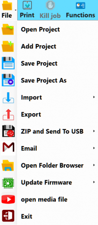
The File menu (shown to the right) has the following options:
- Open Project will open a HyProj (Hyrel Project) on a blank build area, including multiple elements as scaled/rotated/positioned.
- Add Project will add another HyProj to the current build area.
- Save Project will save all elements as displayed as a HyProj.
- Save Project As will save the HyProj as displayed with a name and location of your choosing.
- Import has the following submenu options:
- Slic3r, Default Recipes has the following submenu options:
- All Recipes will import All of our Slic3r recipes into their default locations, overwriting anything with the same names.
- All Print Recipes will import our Print recipes into their default locations, overwriting anything with the same names.
- All Printer Recipes will import our Printer recipes into their default locations, overwriting anything with the same names.
- All Filament Recipes will import our Filament recipes into their default locations, overwriting anything with the same names.
- STEP IGES FILE will allow you to designate a single STEP or IGES file to be loaded to be processed to generate GCODE.
- Slic3r, Default Recipes has the following submenu options:
- Export will export the STL file(s) and save them to disk.
- Zip and Send To USB has the following submenu options - all written to the first USB drive detected:
- REPETREL will create a .rar file of your entire C:\Repetrel directory.
- REPETREL\BIN will create a .rar file of your C:\Repetrel\bin directory.
- SLIC3R wil make a .rar file of your slic3r program folder.
- Slic3r Recipes will make separate .rar files of your Printer, Print, and Filament recipe diretories.
- Screen Shot will save a capture of the Repetrel screen (with no filename extension - just "ScreenShot", but Paint will open it).
- Project with Source Files will currently do nothing (v4.001_A).
- Screen Shot To Project Folder will currently do nothing (v4.001_A).
- Project GCODE will only work if you've opened a "Job" file.
IPrusa Recipes will export your Prusa recipes.
- Email has the following submenu options; they only work if you've configured Repetrel with your email credentials.
- Slic3r Settings
- Project
- Contact Manager
- Screen Shot
- Open Folder Browser has the following submenu options:
- Last Part GCODE Folder will open the directory from which the last GCODE file was opened.
- Last Part STL Folder will open the directory from which the last STL file was opened.
- Repetrel/Bin will open the C:\repetrel\bin directory.
- Default Network Location will open your default network location.
- Slic3r Recipes has the following submenu options:
- Print Recipes will open C:\Users\Hyrel\AppData\Roaming\Slic3r\print.
- Printer Recipes will open C:\Users\Hyrel\AppData\Roaming\Slic3r\printer.
- Filament Recipes will open C:\Users\Hyrel\AppData\Roaming\Slic3r\filament.
- Update Firmware has the following submenu options:
- HotHead Controller will launch the application to flash new firmware on your 103 hothead/hotbed controllers.
- 407 Motion Controller will launch the application to flash new firmware on your 407 or 429 motion controller.
- Open Media File will open whatever media file you select.
- Exit will close and exit the Repetrel program.
- open media file will open a folder browser to open .wmv files.
The Print button will cause the printer to commence executing the files in your tree view that represent actions (GCODEs, converted DXFs, etc.).
Kill job
The Kill job button will cause the printer to cancel whatever job is currently running.
Functions
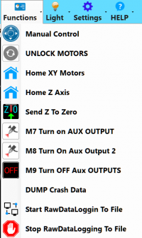
The Functions menu (shown to the right) has the following options:
- Manual Control will bring the Control Tab to the foreground of the Left Side Area.
- UNLOCK MOTORS will disengage (unlock) the motors controlling X, Y and Z positioning, allowing for manual movement.
- Home XY Motors will send the following commands:
- G28 X0 Y0 - this sends the X and Y to the home position;
- G92 X0 Y0 - this resets the home location to the current position; and
- G0 X0 Y0 - this tells the X and Y to move to the home position (where they already are).
- Home Z Axis does nothing at present.
- Send Z to Zero will send a G0 Z0 command, sending the bed and/or yoke in the Z axis to the programmed Z position.
- M7 Turn on AUX OUTPUT will send an immediate M7 command to energize the Aux Output 1 connection (mist on CNC).
- M8 Turn On Aux Output 2 will send an immediate M8 command to energize the Aux Output 2 connection (flood on CNC).
- M9 Turn OFF Aux OUTPUTS will send an immediate M9 command to de-energize both Aux Output connections.
- DUMP CRASH DATA will send M777 S1 to the printer, and should make a data dump helpful for diagnosing troubles.
Light
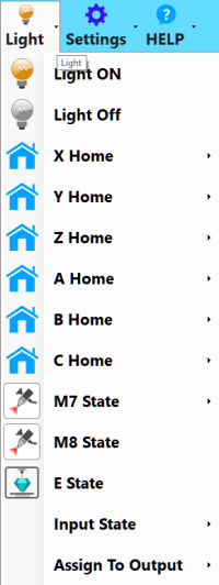
The Light menu (shown to the right) has the following options for the X-Arm (ESR, EHR, 30M) or Gantry (Hydra 16A) printers. Please note that not all of these features (or axes) are available on all models:
- Light On will send an M672 S01 command, turning on the light.
- Light Off will send an M670 S00 command, turning off the light.
- X Home will send an M672 S10 command, so the light toggles when the X axis Home sensor is tripped. It ALSO has a sub-menu:
- X Limit1 will send an M670 S11 command, so the light toggles when the X axis Limit1 is reached.
- X Limit2 will send an M670 S12 command, so the light toggles when the X axis Limit2 is reached.
- X STALL will send an M670 S13 command, so the light toggles when the X motion is stalled.
- X Drv Err will send an M670 S14 command, so the light toggles when the X driver has an error.
- Y Home will send an M672 S20 command, so the light toggles when the Y axis Home sensor is tripped. It ALSO has a sub-menu:
- Y Limit1 will send an M670 S21 command, so the light toggles when the Y axis Limit1 is reached.
- Y Limit2 will send an M670 S22 command, so the light toggles when the Y axis Limit2 is reached.
- Y STALL will send an M670 S23 command, so the light toggles when the Y motion is stalled.
- Y Drv Err will send an M670 S24 command, so the light toggles when the Y driver has an error.
- Z Home will send an M672 S30 command, so the light toggles when the Z axis Home sensor is tripped. It ALSO has a sub-menu:
- Z Limit1 will send an M670 S31 command, so the light toggles when the Z axis Limit1 is reached.
- Z Limit2 will send an M670 S32 command, so the light toggles when the Z axis Limit2 is reached.
- Z STALL will send an M670 S33 command, so the light toggles when the Z motion is stalled.
- Z Drv Err will send an M670 S34 command, so the light toggles when the Z driver has an error.
- A Home will send an M672 S40 command, so the light toggles when the A axis Home sensor is tripped. It ALSO has a sub-menu:
- A Limit1 will send an M670 S41 command, so the light toggles when the A axis Limit1 is reached.
- A Limit2 will send an M670 S42 command, so the light toggles when the A axis Limit2 is reached.
- A STALL will send an M670 S43 command, so the light toggles when the A motion is stalled.
- A Drv Err will send an M670 S44 command, so the light toggles when the A driver has an error.
- B Home will send an M672 S50 command, so the light toggles when the B axis Home sensor is tripped. It BLSO has a sub-menu:
- B Limit1 will send an M670 S51 command, so the light toggles when the B axis Limit1 is reached.
- B Limit2 will send an M670 S52 command, so the light toggles when the B axis Limit2 is reached.
- B STALL will send an M670 S53 command, so the light toggles when the B motion is stalled.
- B Drv Err will send an M670 S54 command, so the light toggles when the B driver has an error.
- C Home will send an M672 S60 command, so the light toggles when the C axis Home sensor is tripped. It ALSO has a sub-menu:
- C Limit1 will send an M670 S61 command, so the light toggles when the C axis Limit1 is reached.
- C Limit2 will send an M670 S62 command, so the light toggles when the C axis Limit2 is reached.
- C STALL will send an M670 S63 command, so the light toggles when the C motion is stalled.
- C Drv Err will send an M670 S64 command, so the light toggles when the C driver has an error.
- Output 1 will send an M672 S71 command (under development).
- Output 2 will send an M672 S72 command (under development).
- Output 3 will send an M672 S73 command (under development).
- Output 4 will send an M672 S74 command (under development).
- Output 5 will send an M672 S75 command (under development).
- Output 6 will send an M672 S76 command (under development).
- Output 7 will send an M672 S77 command (under development).
- Output 8 will send an M672 S78 command (under development).
- M8 State (under development)
- E State will toggle the light when executing extrusion moves. Sorry.
- Input State (under development) It ALSO has a sub-menu:
- Input 1 will send an M672 S71 command (under development).
- Input 2 will send an M672 S72 command (under development).
- Input 3 will send an M672 S73 command (under development).
- Input 4 will send an M672 S74 command (under development).
- Input 5 will send an M672 S75 command (under development).
- Input 6 will send an M672 S76 command (under development).
- Input 7 will send an M672 S77 command (under development).
- Input 8 will send an M672 S78 command (under development).
- Assign To Output (under development) It ALSO has a sub-menu:
- HSS 1 (M7) will send an M672 O0 command (under development).
- HSS 2 (M8) will send an M672 O1) command (under development).
- HSS 3 will send an M672 O2 command (under development).
- HSS 4 will send an M672 O3 command (under development).
- HSS 5 will send an M672 O4 command (under development).
- HSS 6 will send an M672 O5 command (under development).
Settings
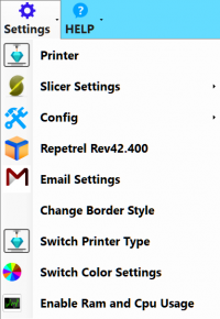
The Settings menu (shown to the right) has the following options:
- Printer will launch the Printer Settings configuration tool, which has three tabs:
- The Printer tab allows for configuration of G0 Rapid Movement Rates, Park parameters, Home Parameters, and Actions after Job Kill.
- The Printer Shape tab allows for configuration of Print Area, Travel Limits, Dump Area, and Custom Pulses per Millimeter settings in each axis. Most users should NEVER change these settings.
- The Advanced tab has options for post-slicing filters.
- Slicer Settings will actually launch the Slic3r homepage in the Web Browser tab.
- Config has the following options:
- Language has options for various languages.
- Set Working Bin Directory will allow you to select a different working directory. Use with caution.
- Repetrel general configuration allows for a few configuration changes.
- Sound Configuration allows for audio notifications of certain events.
- FTP allows for storage of a default FTP credentials.
- Repetrel displays the version of Repetrel which you are currently using. The Repetrel Updates option is not presently working.
- Email Settings allows for storage of a default email credentials.
- Change Border Style toggles display of a window border, allowing for resizing and repositioning. Note that with the border displayed, some portions of the Repetrel interface may not be displayed.
Help
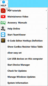
The HELP menu (shown to the right) has the following options:
- PDF tutorials has the following options:
- 1. Hyrel_Quickstart gives a quick overview of unpacking, setting up, and printing.
- 2. Hyrel_Intro_EMO gives a review of the first training session, including printing with the EMO-25.
- 3. Hyrel_MK1_Single gives a review of the second training session, including printing with the MK1-250.
- 4. Hyrel_MK1_Multiple gives a review of the advanced training session, including parallel (clone) and series (cooperative) printing with multiple heads.
- Video Tutorials does nothing at present.
- Maintenance Video does nothing at present.
- Accessory Manuals has the following options:
- Drill Mill Head Manual explains the ST1 Spindle Tool.
- EMO 25 Manual explains the EMO-25 print head.
- HotHead Controller Schematic - 102081_1 explains the 103 Controller Board.
- HotHead SDK explains the Software Developer's Kit for print heads.
- MK1 250 Manual explains the MK1-250 print head.
- Shark V Laser Manual explains the modular laser heads.
Power Indicator, Clock
The Power Indicator shows battery charge / AC power. The Clock shows the current time.
RESET
The RESET button will initiate a soft reset of the 407 Motion Controller.
ALARM
The ALARM button will actually force Repetrel to the background, enabling viewing of other windows.
Left Side Area
The content of the Left Side Area is dynamic, changing depending on which of the Left Side Tabs you have selected:
3D View
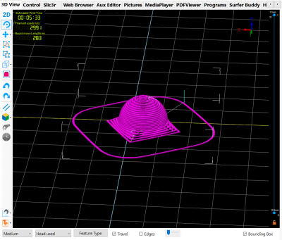
The 3D View tab (shown to the right) displays a rendering of the build area above a log of selected messages. The icons to the left allow one to:
- Alternate between 2D and 3D View
- Rotate the view
- Move opens the submenu to move the:
- Camera
- Object
- Selection
- Group selected objects for group modification
- Ungroup the selected group
- Change Orientation of the view to:
- ORTHO View - looking from the front and above
- TOP View - looking from above, centered
- Front View - looking from the front, centered
- Back View - looking from the back, centered
- Bottom View - looking from the bottom, centered
- Side View - looking from the side, centered
- Use Ortho Zoom
- Undo
- Redo
- Parallel Projection (under development)
- 3D Cube has options to:
- Union - this will combine two STL files into a single STL as positioned
- Subtract - this will evacuate the area of one STL from another as positioned
- Intersection - this will generate a new STL where two others intersect as positioned
- Flip Horizontal - actually createsa mirror image in the Y axis
- Flip Vertical - actually creates a mirror image in the X axis
- 'Pick allows you to click on a line of rendered gcode and have that line highlighted in the gcode window
- Simulate Mode allows a visualization of the print, line by line
- Grid Snap has options to lock your STL dragging to discrete increments:
- Grid Snap OFF
- Grid Snap 1.0mm
- Grid Snap 5mm
- Grid Snap 10mm
- Grid Snap 25mm
- Visualization Settings has options to configure your visualization:
- Show Print Bed
- Show Fixtures
- Copy Image to Clipboard
- Set PrintBed Grid Spacing
- 1 mm
- 2.5 mmmm
- 10 mm
- 25 mm
- Set PrintBed Color
- Set BackGround Color
- Set Selected Object Color
The menus across the bottom allow you to:
- Select Rendering Resolution
- Simple
- Medium
- Fine
- Ultra Fine
- Select Colorization
- Head used
- Feature Type
- Color Type
- Travel (show/hide non-printing moves)
- Edges (under development)
- Bounding Box (show/hide X/Y/Z extents of object)
The System Info window, formerly below the 3D View area, is now on the right side, under Interface > System Info
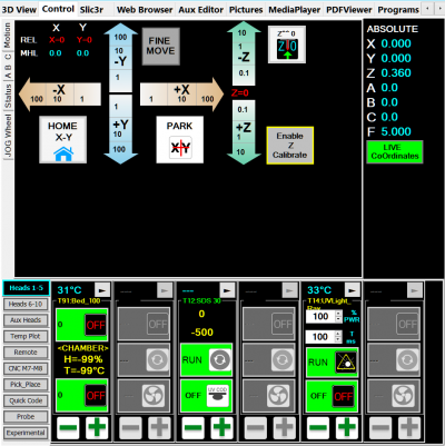
Control
The Control (formerly Manual Control) tab (shown to the right) has Top and Bottom halves; each half has multiple side tabs. The first tab displayed, the Manual tab (Top) and the Head CTRL tab (Bottom) are the primary tabs. The other Top Tabs (Advanced, Table, and Debug) are only used in testing at present. The other Bottom tab (Temp Plot) is used by some users.
Motion
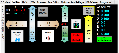
The Motion side tab, in the top portion of the Control tab, deals with manually directing the X/Y/Z motion of the printer, and manually setting the Z-Zero position.
- The Positioning Data will display the current REL (relative) positioning. This is used when calibrating the head offsets. MHL is under development.
- The Tan X arrows will move the yoke or bed (model dependent) by the displayed distance, in the displayed direction (if within programmed range).
- The Blue Y arrows will move the yoke or bed (model dependent) by the displayed distance, in the displayed direction (if within programmed range).
- The Green Z arrows will move the yoke or bed (model dependent) by the displayed distance, in the displayed direction (if within programmed range).
- The Home X-Y button will send the yoke and/or bed (model dependent) to the home positions - X0 Y0.
- The Home Z button (EHR only) will send the yoke up to the home position - normally Z120.
- The Park XY button will send the yoke and/or bed (model dependent) to your preconfigured Park location.
- The Fine Move button will change the X/Y/Z arrows to use smaller distances for fine tuning offsets.
- The Z^^0 button will send the bed up to the user-set (or default) Z-Zero setting. See the Z Calibrate entry, below.
- The Z=50 button will set the current Z position to 50, rather than 0, for use with the toolsetter.
- The Enable Z Calibrate button will enable the Yellow SET Z arrow, below. This should only be enabled when actually setting the Z-Zero.
- The Yellow SET Z arrow will allow the bed to move up past the current Z-Zero position, AND it will set a new Z-Zero position at the Z location to which you move the bed. Note: not for use with EHR models, where a Z offset is applied instead.
ABC
The ABC tab offers manual control of A, B, and C axes. A is normally used with the 4th axis Lathe option. A and B are normally used with the 4th and 5th axis Trunion option. C is used for extrusion or rotation rate of the tool, and is normally controlled on the head itself.
Status
The Status tab is what comes to the front during execution of code.
Jog Wheel
The Jog Wheel tab is used to control the optional Jog Wheel for adjustments - standard on newer Hydra models.
Head CTRL
The Head CTRL side tab, in the bottom portion of the Control tab, deals with manually setting or changing the data on the modular heads. These shots are taken from the display of an MK1-250 head:
- The numbers shown in blue represent the current Temperature in degrees Celsius. If this shows XXX or a very unrealistic temperature, it means your head either has no RTD (thermal reading device), or is set as the wrong type of RTD. The temperature also acts as a "first" (2.855 and earlier) or "previous" (newer versions) page button, depending on the release.
- To the right of the temperature is a Right-arrow, which will allow you to page through the data on the head.
- MK1 is the first page displayed on a head flashed as an MK1-250.
- The first box is the Temperature box, which when not engaged, will show as green, displaying 0 degrees with an "OFF" icon; and when engaged will show as yellow, displaying the default temperature with an "ON" icon.
- The second box is the RUN box, which, when not engaged, will show as green, displaying the word "RUN" and a grey motor icon; and when engaged will show as yellow, displaying the default manual speed (typically 500 pulses per second), and arrows on the motor icon.
- The third box is the FAN (or, on some heads, crosslink) box, which when not engaged will show as green, displaying the word "OFF" and a fan icon; and when engaged will show as yellow, displaying the duty cycle of the fan (or LEDs), and a circle around the fan blades.
- Material is the second page dipslayed.
- The first item will show "ABS>235" or some other setting (including "CUSTOM"), indicating the Default Material and temperature selected.
- The second item will show what Color the temperature plot will render for this head.
- The third item will display the presently set Nozzle Diameter for the head. 'It is critical for proper flow calculations that this number is accurate.'
- The fourth item will display the default Layer Thickness in mm. This will later be overwritten by gcode.
- Temp Info is the third page.
- Print Temp shows the default temperature to which the head will be set, should you manually turn it on. On print jobs, this should be overwritten by gcode.
- PwrFactor should normally be set to 100 percent.
- MIN and MAX should list the safe operating range of the head as programmed.
- OverRides is the fourth page.
- Pulses/nl should actually be "Pulses per Ten Nanoliters" by definition; this defines how many pulses to the motor will advance ten nl of material. 'It is critical for proper flow calculations that this number is accurate.' Unless you are using oversized or undersized filament, you should not have to adjust these numbers.
- The Clone Head button will cycle through options to clone (duplicate the work of) any of the other three heads, as well as a "Clone Off" mode. This allows multiple heads to simultaneously execute gcode written for a single head.
- The Material Flow Rate Multiplier' allows for an easy, LIVE, percentage-based increase or decrease to the flow calculations. 1.000 is the default; 1.05 would generate 5% more flow.
- Prime is the fifth page. We define a Prime as an advance of material whenever transitioning from a non-printing move to a printing move. It can be customized for your particular material as follows:
- Steps means how many steps or pulses the feed motor will be advanced during a Prime move.
- The RATE at which the Prime will occur should normally be 10,000 (pulses per second).
- The Dwell Time in milliseconds indicates how long after the Prime has begun before the flow rate of the next move should be engaged.
- # Primes After Tool change allows for multiple cycles of Priming after this tool is reactivated by a tool change command.
- UnPrime is the sixth page. We define an UnPrime as a retract of material whenever transitioning from a printing move to a non-printing move. It can be customized for your particular material as follows:
- Steps means how many steps or pulses the feed motor will be retracted during an unPrime move.
- The RATE at which the UnPrime will occur should normally be 10,000 (pulses per second).
- The Dwell Time in milliseconds indicates how long after the UnPrime has begun before the flow rate of the next move should be engaged; as the following flow rate is zero (for the non-printing move), this number is immaterial.
- # Unprimes B4 Tool change allows for multiple cycles of UnPriming before this tool is temporarily deactivated by a tool change command.
- offsets is the seventh page. This is where we can set a Master head (for cloning), as well as set the tool offsets for heads which work cooperatively on the same print. This can be on different stls which print together, as well as support material from another head.
- Setup As Master will home the bed and yoke, and set the selected head as the Master head for potential Clone heads.
- X is where you can set or read the X offset in mm for a Clone head from the Master head.
- Y is where you can set or read the Y offset in mm for a Clone head from the Master head.
- Z is where you can set or read the Z offset in mm for a Clone head from the Master head. In all cases using print heads only, this should always be zero. The Z offset is used for the milling and lasing tools.
- GOTO X/Y will send the head to its offesets.
- Grab will grab the currently displayed offsets for this head.
- Head Info is the eighth page.
- Model shows with what model choice the current head is programmed
- RTD Type shows what RTD Lookup tables should be used. This should be "1Meg" for older heads and "1k PLAT_RTD" for newer (Dec 2015 and later) heads.
- Motor Current should be set to High
- Step Mode' should be set to Sixteenth
- Soap String is the ninth and final page, and it is from here that you can store or discard any changes you've made.
- Right-clicking on the Flash button will allow you to flash the displayed values to the head as new defaults going forward
- The Soaper Ref data is sometimes helpful in debugging issues
- The Reset button will re-read data from the head, discarding any change you've made
- The READ button will display the device type, hardware and software versions, and key data from the head.
Temp Plot
The Temp Plot side tab, in the bottom portion of the Control tab, allows users to view heating and cooling data. Right-clicking on the plot area will give a menu allowing for various options, including saving the data, opening previously saved data, and toggling on/off set points, actual temperatures, and duty cycles.
Pictures
asdf
Web Browser
Since the Repetrel interface takes up the entire tablet screen, there is a built-in web browser to allow reference or other pages to be loaded.
Aux Editor
The Aux Editor tab provides numerous functions:
- Print GCode is where selected messages from the slicing log are displayed, including any errors.
- AUX EDITOR is a workplace where you can paste, edit, and copy gcode or other text.
- G-Code Dictionary lists our G- and M- Codes, with examples and descriptions. This file is also readable by opening C:\repetrel\data\G-Code dictionary.csv in any spreadsheet or CSV editor.
- snapped picture is where the latest image captured through the Camera tab or an M790 is displayed.
Help
This is where any videos or PDFs selected from the HELP menu will be displayed.
Slic3r
The Slic3r tab is where the Slic3r interface will be loaded, either for editing recipes or configuring multi-stl, multi-head prints.
Programs
This is where the paths to various programs are stored, so that external calls from Repetrel may be made.
Right Side Area
The content of the Right Side Area is dynamic, changing depending on which of the Right Side Tabs you have selected:
Project Composer, Upper
The top of the Project Composer tab has a menu; the middle has a project tree view on the left and a set of tabs on the right, and the bottom has a set of side tabs, which we will visit in more depth below.
OffSets
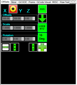
The Offsets tab allows the user to:
- Position (Offsets zone) the selected model in the X, Y, or Z axis.
- Scale the selected model with the aspect ration maintained (default), or individually along the X, Y, or Z axis.
- Rotate the selected model about the X, Y, or Z axis.
Note:
- The mm button will toggle the scale between 0 and 24.5, for easy switching between inches and millimeters.
- The target button will roughly center the 0,0 point of the model on the bed, with the lowest point flush to the bed.
- The down arrow button will realign the object so that the lowest point is flush to the bed.
- The lock XYZ button will ensure that scaling is applied equally to all axes.
- The 15 Deg button indicates that the + and - buttons will increment the rotation by 15 degrees with each click.
- The 'double up' and 'double down' arrows affect the selected object's positioning in the highlighted axis.
- All of the up/down arrows next to numbers will increment that value by one with each click.
Slicer
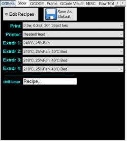
The Slicer tab is where we select the recipes with which to slice the model, or convert it into layers of gcode. It also has an "Edit Recipes" button, which launches the recipe configuration tool.
- The Edit Recipes button will launch the Slic3r configuration tool, where recipes can be viewed, edited, and saved.
- The Save As Default button will make the currently displayed recipes defaults for the interface.
- The Print: dropdown menu is used to select the Print recipe, which defines the physical placement of material, including: the number of solid top and bottom layers and perimeters in the XY plane; the infill pattern and density; the print speed; which heads do which portions of the print (if slicing for multiple heads); and the extrusion width (how far apart the paths should be centered - normally the nozzle diameter plus 10%; and other parameters.
- The drill-laser recipe box allows the user to select a series of saved parameters for converting files to gcode for a laser or spindle tool; this is superceded by the Prams tab.
GCODE
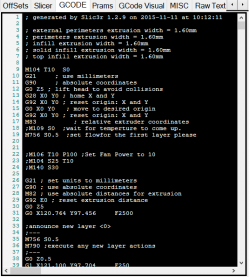
This is where the actual gcode file currently selected in the tree view is displayed, and can be edited.
Note that when a job is started, this gcode is coped to a protected location, and any changes made during a print will not affect the present print, but will affect future prints. These changes are not automatically saved to disk, so please do so manually (right click and select a file name and location) if you want to save any changes.
Also, you can right-click in the gcode window and insert modifications at the point of the cursor (like "change fan speed to..."), as well as clicking on the Edit menu and selecting options including inserting a raft and making a tool change.
If multiple gcodes are open in the tree view, this will display the one highlighted (in green) in the tree view. If multiple gcodes are in the tree view at the start of the job, they will be executed in the order displayed.
Prams
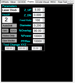
The Prams tab allows the user to customize the parameters used to convert a simple dxf file into gcode for the laser or spindle tool.
- Under the word Parameters is a dropdown box for selecting the type of tool for which we are slicing.
- The Head# box allows the user to select which head (tool position) will be executing this gcode.
- Auto Drill Code is presently disabled.
- ZUp controls how much distance should be introduced for non-printing moves (so the bit does not drag through material which is to remain during "non-printing" (or "non-milling") moves.
- ZDown is presently unused.
- Feed Rate is the linear travel speed in the XY plane (just like when printing) in mm/min.
- Diameter is the diameter of the bit being used. This is needed so that positioning will be offset, allowing the edge of the tool to remove the proper amount of material.
- %Power is the percent of full power at which the drill or laser should operate.
- Tool Change XYZ specifies the movement during tool changes.
GCODE Visual
Unused in the current release.
MISC
Unused in the current release.
Raw Text
This is where Drill/Mill gcode is temporarily written. These contents are used with the Zebra Print function.
The Raw Text window shouldn't list any starting or ending gcode, as this will be repeated on each Zebra Print layer.
Zebra Prints
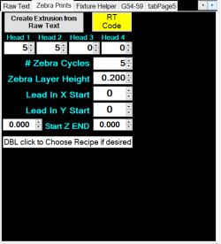
This takes one layer of gcode and generates a multi-layer gcode file, repeating the current pattern (displayed in the Raw Text tab) in the number of cycles the user configures.
- Create Extrusion from Raw Text will use the parameters displayed to generate a multi-layer print from your single layer gcode in the Raw Text window.
- RT Code is always enabled.
- The Head 1 number determines how many layers from this head per cycle.
- The Head 2 number determines how many layers from this head per cycle.
- The Head 3 number determines how many layers from this head per cycle.
- The Head 4 number determines how many layers from this head per cycle.
- The # Zebra Cycles number determines how many cycles of the above pattern will be repeated.
- The Zebra Layer Height number indicates the layer thickness of all layers.
- The Lead In X Start is the X-axis offset for positioning the gcode.
- The Lead In Y Start is the Y-axis offset for positioning the gcode.
- The Circle Edge X Start ...
- The Circle G2 Radius ...
Pick_Place
Unused in the current release.
Fixture Helper
Unused in the current release.
G54-59
Unused in the current release.
Project Composer, Lower
The lower area of the Project Composer tab has sub-tabs, providing the following functionality:
FIND
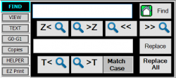
This tab houses tools for manipulating and searching your gcode file.
- The upper text box can hold a search string. Note that GCode is case sensitive, and all commands must be upper case.
- The Find button, with a house icon and the word Find, will search for the first instance of the search string, starting at the home (beginning) of the file presently selected.
- The Previous Layer button, with the text Z< and a magnifying glass icon, will scroll up from the current cursor position to the previous layer announcement. Note: not working on Repetrel v2x.
- The Next Layer button, with a magnifying glass icon and the text Z<, will scroll down from the current cursor position to the next layer announcement.
- The Search Backward button, with a magnifying glass icon and the text <<, will search backward from the current cursor position for the string in the search box. Note: not working on Repetrel v2x.
- The Search Forward button, with a magnifying glass icon and the text <<, will search Forward from the current cursor position for the string in the search box.
- The lower text box can hold a replace string.
- The Replace button will replace the currently highlighted text with the string in the lower text box. Note: not working on Repetrel v2x.
- The Previous Toolchange button, with the text T< and a magnifying glass icon, will scroll up from the current cursor position to the previous toolchange. Note: not working on Repetrel v2x.
- The Next Toolchange button, with a magnifying glass icon and the text >T, will scroll down from the current cursor position to the next toolchange.\
- The Match Case button will toggle the search function between being case sensitive (when the button is outlined in blue) and not case sensitive (the default).
- The Replace All button will replace all occurrences of the string in the upper box with the string in the lower box. Note: not working on Repetrel v2x.
VIEW
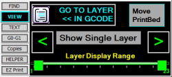
This tab houses tools for viewing the rendering of printing moves in your gcode file.
- The GO TO LAYER << IN GCODE button will send you to the layer change announcement line in your gcode file.
- The Move PrintBed button will move the print bed to the Z position for the layer presently displayed.
- The Show Single Layer button will display one layer at a time in the gcode rendering.
- When Show Single Layer is enabled, the < button will display the previous layer in the gcode rendering, allowing you to scroll backward, layer by layer.
- When Show Single Layer is enabled, the > button will display the next layer in the gcode rendering, allowing you to scroll forward, layer by layer.
- The Layer Display Range slider allows you to display a subset of layer (including a single layer) of the gcode rendering.
TEXT
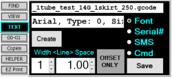
This tab houses the controls for creating text objects, primarily for use with the laser and spindle tool heads. This tool creates the pathing to outline each character.
- The first text box is where you enter the text for which you want tool paths generated.
- The Font, Serial#, SMS, and Cmd options change the configuration of the text generator for different functions:
- The Font button allows...
- The Serial# button allows for the creation of sequential serial numbers.
- The SMS button allows...
- The Cmd button allows...
- The second text box is...
- The Create button executes the configuration as detailed by the other options.
- The Width button allows the text outlining to be wider.
- The <Line> Space button allows adjustment of vertical line spacing.
- The OffSET ONLY button...
- The Save button saves...
G0-G1
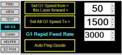
This tab allows you to post-process the selected gcode file.
- When clicked, the Set All G1 Speed To > button will change all G1 moves to the new value displayed to the right.
- The G1 Rapid Feed Rate number shown is the upper limit on which G1 moves will be modified when the Set All G1 Speed To > button is clicked.
- When clicked, the Set G1 Speed from > this Layer forward > button will limit which G1 moves will be modified from this layer (shown to the right) forward.
- The 'Auto Prep Gcode button will post-process the gcode to add a non-zero E value to every non-printing G1 move of less than 1.1mm. This eliminates unnecessary retract/advance cycles, and gives a smoother finish.
Copies
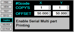
This tab is still in development and would allow for multiple copies to be printed, either one at a time, or layer by layer across all copies.
HELPER
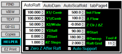
This tab is still in development and will allow for the automatic generation of gcode to create rafts, dams, and scaffolds to enhance printing.
EZ Print
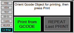
This tab allows for easy printing of simple models with default recipes, or repeating the last print.
Comm Link
asdf
Camera
asdf
Live Video
Capture Picture
Live Canny
TabPage4
TabPage5
3DVisualSettings
asdf
