Difference between revisions of "Firmware"
| (57 intermediate revisions by the same user not shown) | |||
| Line 4: | Line 4: | ||
| __TOC__ | | __TOC__ | ||
|} | |} | ||
New software will often require new firmware. New software packages always come with the latest firmware at the time the software was released; however, sometimes newer firmware is available. | |||
There are two families of firmware; one for the '''Heads and Beds''', or STM-103 boards, and another for the '''Motion Controllers''', or STM-427 / STM-407 boards. | |||
These steps are performed in this video: https://www.youtube.com/watch?v=9qbUzZM3vtg | |||
== '''Motion Controllers''' == | |||
To find out what version of <span style="color: blue;">Motion Controller Firmware</span> you are on now: | |||
[[File:Rep_mc_version_info.png|750px]] | |||
'''<span style="color: | Legend: | ||
<span style="color: red;">'''RED''' text shows the version of '''SOFTWARE'''.</span><br> | |||
<span style="color: blue;">'''BLUE''' text shows the version of '''FIRMWARE'''.</span><br> | |||
<span style="color: magenta;">'''MAGENTA''' text shows the '''COMMUNICATIONS PROTOCOL''' - USB or UART with port number.</span> | |||
=== Motion Controller Switches === | |||
Your motion controller (<span style="color: green;">green '''STM407''' on ESR and 30M printers</span>, or <span style="color: blue;">blue '''STM32''' on Hydra and EHR printers</span>) has two switches. | |||
<span style="color: red;">The '''BOOT CONFIG''' switch can be set to '''SYSTEM''' (usually up or left - sometimes needed for flashing firmware) or '''FLASH''' (usually down or right). '''It should be set to FLASH for normal operations.'''</span> | |||
<span style="color: purple;">The unlabeled power switch can be set to '''USB''' (usually left or down - you should not need to use this setting) or '''5Vin'''. '''It should be set to 5Vin for normal operations.'''</span> | |||
<span style="color: dodgerblue;">Note the '''RESET''' button, shown here above the USB connector and the LED. '''You need to RESET after changing any switch positions.''' All current printers also have a '''RESET''' button on the outside or inside of the chassis.</span> | |||
Images: | |||
[[File:407_switches.jpg|500px]] [[File:429_switches.jpg|500px]] | |||
=== Motion Controller Firmware === | === Motion Controller Firmware === | ||
| Line 51: | Line 58: | ||
# You are done. | # You are done. | ||
{| border="1" class="wikitable" style="width: | {| border="1" class="wikitable" style="width: 80%;" | ||
|+ Firmware Listing | |+ Firmware Listing | ||
! style="width: 20%;" | Printer Model | ! style="width: 20%;" | Printer Model | ||
| Line 58: | Line 65: | ||
|- | |- | ||
!rowspan="2"| All Hydra Models ''(3-, 4- and 5- axis)'' | !rowspan="2"| All Hydra Models ''(3-, 4- and 5- axis)'' | ||
| '''Repetrel 4. | | '''Repetrel 4.2.431''' | ||
| ''' | | '''EngineHR_Hydra_4.200l.dfu''' (L) | ||
|- | |- | ||
| Repetrel 3.084c | | Repetrel 3.084c | ||
| Hydra 3.083m | | Hydra 3.083m | ||
|- | |- | ||
!rowspan="2"| Engine, High Resolution | !rowspan="2"| Engine, High Resolution (EHR) | ||
| '''Repetrel 4. | | '''Repetrel 4.2.431''' | ||
| ''' | | '''EngineHR_Hydra_4.200l.dfu''' (L) | ||
|- | |- | ||
| Repetrel 3.084c | | Repetrel 3.084c | ||
| Hydra 3.083m | | Hydra 3.083m | ||
|- | |- | ||
!rowspan="4"| System 30M ''(and earlier Systems)'' | !rowspan="4"| System 30M ''(and earlier Systems)''<br>and Engine, Standard Resolution (ESR) | ||
| '''Repetrel 4. | | '''Repetrel 4.2.431''' | ||
| ''' | | '''EngineSR_30M_4.200l.dfu''' (L) | ||
|- | |- | ||
| Repetrel 3.084c | | Repetrel 3.084c | ||
| Line 82: | Line 89: | ||
|- | |- | ||
| Repetrel 1.85 | | Repetrel 1.85 | ||
| Version 1.85 | | Version 1.85 | ||
|- | |- | ||
|} | |} | ||
=== Motion Controller Values === | === Motion Controller Values === | ||
| Line 111: | Line 103: | ||
Please resist the urge to go tampering here without talking to us. There's probably a better way to achieve your desired end results. | Please resist the urge to go tampering here without talking to us. There's probably a better way to achieve your desired end results. | ||
== '''Heads and Beds''' (STM103 boards) == | |||
To find out what version(s) of <span style="color: orange;">Head/Bed Firmware</span> you are on now: | |||
== V2 vs V3 vs V4 == | |||
'''<span style="color: red;">Why is my head FLASHING RED?</span>''' | |||
Non-Hydra units shipping through spring 2017 shiped with Repetrel version 2.x, and should be on the last version 2 release. | |||
Hydra units, and other units shipping through spring 2019 shipped with version 3.x, and should be on the last version 3 release. | |||
All units shipping after spring 2019 ship with version 4.x, and should be on the last version 4 release. | |||
Please use the files in your C:\Repetrel\bin\firmware directory, since it is "paired" with your Repetrel version. | |||
All units should be upgraded to the latest version when it is available. If you run a head with v2 settings on a v3 or later install, the background will '''<span style="color: red;">FLASH RED</span>'''; this '''DOES NOT''' mean that you need to flash new '''FIRMWARE''' - this '''DOES''' mean that you need to flash new '''VALUES''' to the head. Please make the changes noted for each head and right-click-flash these values on your heads: | |||
# [[Cold_and_Warm_Flow#Settings_for_Cold_and_Warm_Flow_Heads|For Cold and Warm Flow (EMO, SDS, VOL, KRA, TAM, etc).]] | |||
# [[Hot_Flow#Settings_for_Hot_Flow_Heads|For Hot flow (MK*).]] | |||
# For the HotBed Controller, just define it as a print head, set the pulses to 10, redefine it as a hotbed, and flash these settings. Contact us for help. | |||
[[File:Head_bed_version_info_v4.png]] | |||
=== Head / Bed Firmware === | === Head / Bed Firmware === | ||
For the STM-103 Boards. Consult the table below for the proper version. The wrong version WILL NOT WORK. | For the STM-103 Boards. Consult the table below for the proper version. The wrong version WILL NOT WORK. | ||
These files are included in the latest '''[[4_Install|Repetrel]]''' download, and the latest Repetrel\bin directory download. | |||
Video instructions for flashing the 103 (HH/HB) Controllers: https://youtu.be/yM8QMZBTb4o | Video instructions for flashing the 103 (HH/HB) Controllers: https://youtu.be/yM8QMZBTb4o | ||
| Line 125: | Line 140: | ||
# Connect the ST-Link as shown in the video above. | # Connect the ST-Link as shown in the video above. | ||
# Click "Program" - the process takes a few seconds. | # Click "Program" - the process takes a few seconds. | ||
# You are done. | # You are mostly done - you still need to update the settings on each head and the hotbed, but that's easy now - see below. | ||
{| border="1" class="wikitable" style="width: 75%;" | {| border="1" class="wikitable" style="width: 75%;" | ||
| Line 133: | Line 148: | ||
|- | |- | ||
| ALL HEADS | | ALL HEADS | ||
| | | Heads_Beds_103_4.050f.hex | ||
|- | |- | ||
|} | |} | ||
{| border="1" class="wikitable" style="width: 75%;" | {| border="1" class="wikitable" style="width: 75%;" | ||
| Line 143: | Line 157: | ||
! style="width: 50%;" | Firmware | ! style="width: 50%;" | Firmware | ||
|- | |- | ||
| | | MK1-250 | ||
| MK1_2_PRTDClearWires_1A.hex | | MK1_2_PRTDClearWires_1A.hex | ||
|- | |- | ||
| | | MK1-250 '''with red RTDs (from pre-2015) | ||
| _FIL_250_RED_235A.hex | | _FIL_250_RED_235A.hex | ||
|- | |- | ||
| | | MK2-250 | ||
| MK1_2_PRTDClearWires_1A.hex | | MK1_2_PRTDClearWires_1A.hex | ||
|- | |- | ||
| | | MK1-450 | ||
| MK450_Caution_450C_45A.hex | | MK450_Caution_450C_45A.hex | ||
|- | |- | ||
| Line 158: | Line 172: | ||
! Firmware | ! Firmware | ||
|- | |- | ||
| | | ALL Emulsion-Type Heads | ||
| Emo_Vol_Kra_Cod. | | Emo_Vol_Kra_Cod.52V.hex | ||
|- | |- | ||
! Laser Heads and | ! Laser Heads and UV Pens | ||
! Firmware | ! Firmware | ||
|- | |- | ||
| Diode Lasers on Repetrel v2.xs | |||
| Laser_Diode_Shark_6N.hex | | Laser_Diode_Shark_6N.hex | ||
|- | |- | ||
| Diode and CO2 Lasers on Repetrel v3.x | |||
| LaserPWM_8L.hex | | LaserPWM_8L.hex | ||
|- | |- | ||
| Line 173: | Line 187: | ||
! Firmware | ! Firmware | ||
|- | |- | ||
| Spindle Tools, Three-Phase | |||
| 3phase_Spindle_238M.hex | | 3phase_Spindle_238M.hex | ||
|- | |- | ||
| Spindle Tools, Single-Phase | |||
| DrillMill_236M_DC_SPINDLE.hex | | DrillMill_236M_DC_SPINDLE.hex | ||
|- | |- | ||
| Line 182: | Line 196: | ||
! Firmware | ! Firmware | ||
|- | |- | ||
| Inkjet Headss (Heat- and Piezo- based) | |||
| LaserPWM_8L.hex | | LaserPWM_8L.hex | ||
|- | |- | ||
| Line 188: | Line 202: | ||
=== Head / Bed Values === | === Head / Bed Values === | ||
''Note: For CO<sub>2</sub> Lasers, Your acutal laser controller, on the Aux Heads tab, should be set to "Laser_40".''<br> | |||
''Note: For CO<sub>2</sub> Lasers, Your safety/mirror/lens controller, on the Heads 1-5 tab, should be set to "CO2_Laser"'' | |||
Let's not confuse flashing a version of firmware on a head with flashing new default values to a head. I know - I didn't come up with the terms. | Let's not confuse flashing a version of firmware on a head with flashing new default values to a head. I know - I didn't come up with the terms. | ||
| Line 193: | Line 210: | ||
This also used to be a lot of info to change, but now we have made it easier! | This also used to be a lot of info to change, but now we have made it easier! | ||
Right-click on the head and select | Right-click on the head (anywhere EXCEPT the "FLASH" button) and open the proper file for your head or bed: | ||
[[File:Loadfromfile1.png|250px]] | |||
And select the file for the device for which you wish to load the settings: | |||
[[File:Loadfromfile2.png|500px]] | |||
As with all settings, to store them as defaults, go to the last page and right-click FLASH: | |||
[[File: | [[File:Rcflash1.png|500px]] | ||
And then click YES: | |||
[[File:Rcflash2.png|250px]] | |||
Old method: | '''Old method:''' | ||
Once your head has the proper firmware version running on it, you want to be sure that the values for the head are correct. Please consult the pages for [[Reservoir_Heads]] and [[Filament_Heads]] for our recommended values, then adjust for your custom environment as needed, determined through trial and observation. | Once your head has the proper firmware version running on it, you want to be sure that the values for the head are correct. Please consult the pages for [[Reservoir_Heads]] and [[Filament_Heads]] for our recommended values, then adjust for your custom environment as needed, determined through trial and observation. | ||
Latest revision as of 19:20, 19 July 2021
New software will often require new firmware. New software packages always come with the latest firmware at the time the software was released; however, sometimes newer firmware is available.
There are two families of firmware; one for the Heads and Beds, or STM-103 boards, and another for the Motion Controllers, or STM-427 / STM-407 boards.
These steps are performed in this video: https://www.youtube.com/watch?v=9qbUzZM3vtg
Motion Controllers
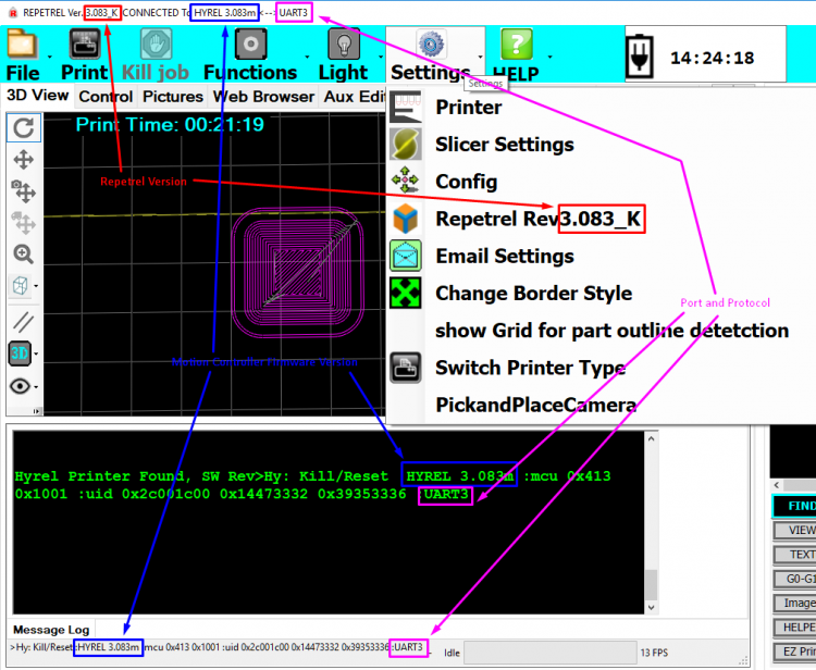
To find out what version of Motion Controller Firmware you are on now:
Legend:
RED text shows the version of SOFTWARE.
BLUE text shows the version of FIRMWARE.
MAGENTA text shows the COMMUNICATIONS PROTOCOL - USB or UART with port number.
Motion Controller Switches
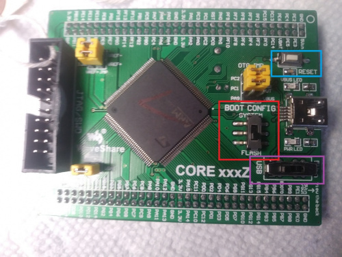
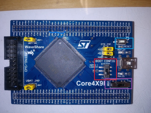
Your motion controller (green STM407 on ESR and 30M printers, or blue STM32 on Hydra and EHR printers) has two switches.
The BOOT CONFIG switch can be set to SYSTEM (usually up or left - sometimes needed for flashing firmware) or FLASH (usually down or right). It should be set to FLASH for normal operations.
The unlabeled power switch can be set to USB (usually left or down - you should not need to use this setting) or 5Vin. It should be set to 5Vin for normal operations.
Note the RESET button, shown here above the USB connector and the LED. You need to RESET after changing any switch positions. All current printers also have a RESET button on the outside or inside of the chassis.
Images:
Motion Controller Firmware
For the STM-429 and STM-407 Boards.
Video instructions for flashing the 407 and 429 (Motion) Controllers: https://youtu.be/cFAFRkpLmww
Note that all units shipped since 2015 are internally cabled to automatically connect for flashing, so there should be no need to remove the rear cover or connect special cables.
You should always use the latest version of the release you are on, and we recommend that you upgrade to the most recent release (but this is not required).
- Launch Repetrel ( C:\Repetrel\bin\Repetrel.exe ).
- Go to File > Update Firmware > Motion Controller
- Select the latest .dfu file for your machine from the table below.
- Your printer should show as "CONNECTED" in the firmware utility. If it is not:
- Access the Motion Controller.
- Change the vertical switch to BOOT CONFIG (away from the vertical switch).
- Reset the motion controller (small button left of the LED).
- You should now be CONNECTED.
- Click "Program" - the process takes a few seconds.
- IF you had to change the switch, change it back and reset the motion controller.
- You are done.
| Printer Model | Repetrel Version | Firmware |
|---|---|---|
| All Hydra Models (3-, 4- and 5- axis) | Repetrel 4.2.431 | EngineHR_Hydra_4.200l.dfu (L) |
| Repetrel 3.084c | Hydra 3.083m | |
| Engine, High Resolution (EHR) | Repetrel 4.2.431 | EngineHR_Hydra_4.200l.dfu (L) |
| Repetrel 3.084c | Hydra 3.083m | |
| System 30M (and earlier Systems) and Engine, Standard Resolution (ESR) |
Repetrel 4.2.431 | EngineSR_30M_4.200l.dfu (L) |
| Repetrel 3.084c | Hyrel 3.083m | |
| Repetrel 2.865 | Version 2.415 | |
| Repetrel 1.85 | Version 1.85 |
Motion Controller Values
Let's not confuse flashing a version of firmware on the motion controller with flashing new default values to the motion controller - again, not my terms.
We should always be sure that we're running not only with the correct version of the motion controller firmware, but that the values for the present model of equipment are being used. In Repetrel, under Settings > Printer, a dialog box will open with lots of numbers you may want to play with. Please don't change any values unless you're sure that they will do something that you want. We have default files for each model, and some users will want to save custom settings - like different park positions for different beds, or different maximum print speeds and acceleration parameters for more heavily outfitted yoke assemblies.
There is a utility to read and write configuration files on every PC running Repetrel v3 at C:\repetrel\Printer Settings, and you should run on (or at least start with) the configuration file for your model printer.
Please resist the urge to go tampering here without talking to us. There's probably a better way to achieve your desired end results.
Heads and Beds (STM103 boards)
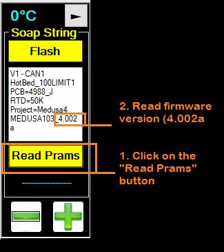
To find out what version(s) of Head/Bed Firmware you are on now:
V2 vs V3 vs V4
Why is my head FLASHING RED?
Non-Hydra units shipping through spring 2017 shiped with Repetrel version 2.x, and should be on the last version 2 release.
Hydra units, and other units shipping through spring 2019 shipped with version 3.x, and should be on the last version 3 release.
All units shipping after spring 2019 ship with version 4.x, and should be on the last version 4 release.
Please use the files in your C:\Repetrel\bin\firmware directory, since it is "paired" with your Repetrel version.
All units should be upgraded to the latest version when it is available. If you run a head with v2 settings on a v3 or later install, the background will FLASH RED; this DOES NOT mean that you need to flash new FIRMWARE - this DOES mean that you need to flash new VALUES to the head. Please make the changes noted for each head and right-click-flash these values on your heads:
- For Cold and Warm Flow (EMO, SDS, VOL, KRA, TAM, etc).
- For Hot flow (MK*).
- For the HotBed Controller, just define it as a print head, set the pulses to 10, redefine it as a hotbed, and flash these settings. Contact us for help.
Head / Bed Firmware
For the STM-103 Boards. Consult the table below for the proper version. The wrong version WILL NOT WORK.
These files are included in the latest Repetrel download, and the latest Repetrel\bin directory download.
Video instructions for flashing the 103 (HH/HB) Controllers: https://youtu.be/yM8QMZBTb4o
- Launch Repetrel ( C:\Repetrel\bin\Repetrel.exe ).
- Go to File > Update Firmware > HotHead Controller (even for HotBeds).
- Navigate to the proper .hex file for your machine from the table below.
- Connect the ST-Link as shown in the video above.
- Click "Program" - the process takes a few seconds.
- You are mostly done - you still need to update the settings on each head and the hotbed, but that's easy now - see below.
| All Heads | Firmware |
|---|---|
| ALL HEADS | Heads_Beds_103_4.050f.hex |
| Filament Heads | Firmware |
|---|---|
| MK1-250 | MK1_2_PRTDClearWires_1A.hex |
| MK1-250 with red RTDs (from pre-2015) | _FIL_250_RED_235A.hex |
| MK2-250 | MK1_2_PRTDClearWires_1A.hex |
| MK1-450 | MK450_Caution_450C_45A.hex |
| Emulsion-Type Heads | Firmware |
| ALL Emulsion-Type Heads | Emo_Vol_Kra_Cod.52V.hex |
| Laser Heads and UV Pens | Firmware |
| Diode Lasers on Repetrel v2.xs | Laser_Diode_Shark_6N.hex |
| Diode and CO2 Lasers on Repetrel v3.x | LaserPWM_8L.hex |
| Spindle Tools | Firmware |
| Spindle Tools, Three-Phase | 3phase_Spindle_238M.hex |
| Spindle Tools, Single-Phase | DrillMill_236M_DC_SPINDLE.hex |
| Inkjet Heads | Firmware |
| Inkjet Headss (Heat- and Piezo- based) | LaserPWM_8L.hex |
Head / Bed Values
Note: For CO2 Lasers, Your acutal laser controller, on the Aux Heads tab, should be set to "Laser_40".
Note: For CO2 Lasers, Your safety/mirror/lens controller, on the Heads 1-5 tab, should be set to "CO2_Laser"
Let's not confuse flashing a version of firmware on a head with flashing new default values to a head. I know - I didn't come up with the terms.
This also used to be a lot of info to change, but now we have made it easier!
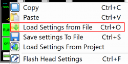
Right-click on the head (anywhere EXCEPT the "FLASH" button) and open the proper file for your head or bed:
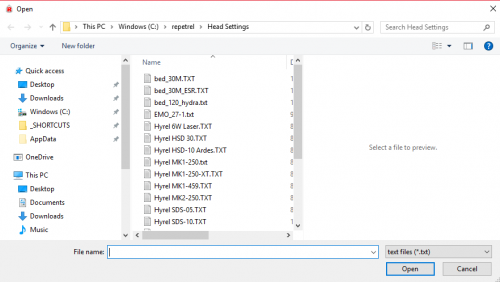
And select the file for the device for which you wish to load the settings:
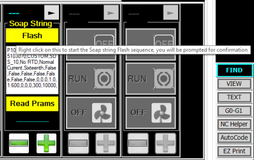
As with all settings, to store them as defaults, go to the last page and right-click FLASH:
And then click YES:
Old method:
Once your head has the proper firmware version running on it, you want to be sure that the values for the head are correct. Please consult the pages for Reservoir_Heads and Filament_Heads for our recommended values, then adjust for your custom environment as needed, determined through trial and observation.
To change the values, click on the arrow at the top right (next page) or the temperature display area at the top left (previous page) of the displayed data for that head. Edit values as appropriate, and then on the last page, RIGHT-CLICK on the Flash button and then confirm that you want to overwrite the previous defaults with these values, then click Yes on the confirmation dialog box.
For our purposes, the hotbed and a printhead are controlled in the same manner.
