Difference between revisions of "FAQs"
| Line 467: | Line 467: | ||
The external button on the ESR and EHR is on the right side and looks like this, although it used to be a green or red button: | The external button on the ESR and EHR is on the right side and looks like this, although it used to be a green or red button: | ||
[[File:Engine_reset.png|200px| | [[File:Engine_reset.png|200px|Engines]] | ||
The remote button on the 16A is located inside, behind the control panel, and looks like this: | The remote button on the 16A is located inside, behind the control panel, and looks like this: | ||
[[File:16A_reset.png|200px|16A]] | [[File:16A_reset.png|200px|16A]] | ||
Revision as of 14:08, 26 January 2021
So, some folks have questions about how they can make certain changes in their prints. I will answer the most frequently asked questions below.
The following all apply to all versions of Repetrel.
Training
Why is there mandatory training?
Here at Hyrel, we believe that no training equals a bad printing experience. We are NOT in business to work hard and then have our customers have a bad experience. We include up to five hours of online training (via Skype and TeamViewer) to ensure that you can get reasonable, reliable results out of your printer. All of our models are compatible with this training.
It is our policy to only sell a printer after we have talked to the customer about their application; the reason for this is that 3D printing is still quite new to the world, and many people have inaccurate ideas of what a printer can do and what it takes to make a good part. We have no interest in selling a printer to a person, only to have them find out it will not work for them. Our mission is to create and sell print systems to people that will use them and find great satisfaction in being our customers.
We have had great experiences with those who have taken this training, as it gives them each a better idea of the printer and its capabilities. Likewise, we have had some bad experiences with a couple of customers who refused the training, and then were unhappy with the product. We believe that our printer is perfect for many customers, but not all customers. Until you have some idea of how it operates, you have no actual first-hand information to make a good decision. And we want our printers to go to people who will use them to do things other printers cannot do.
We have two training sessions that we do one-on-one, and during that session we use teamviewer 9 and Skype, and we allow you to go through the entire design to print process; you actually control the printer from your computer during this session (via TeamViewer) and see the results (via Skype).
If you have a strong interest, then please contact us to set up a session.
How do you do the training?
1. You need to have downloaded and installed regular skype ( https://www.skype.com/en/get-skype/ ) - not the "for business" version - and registered a free account. You don’t need a camera, but you do need a microphone. Direct link: https://go.skype.com/windows.desktop.download
2. You need to have downloaded and installed teamviewer 9 ( https://community.teamviewer.com/English/kb/articles/78348-download-teamviewer-8-and-9 ), the free client for non-commercial use. Direct link: https://download.teamviewer.com/download/version_9x/TeamViewer_Setup.exe
3. You need to be online with skype and teamviewer 9 running, and be logged in to your skype account.
This works best for you if you have two displays (or two computers), with the teamviewer 9 window on one and the skype window on the other, although it does work with one screen (just not as well). To start, you can skype me (hy.rel, johns creek) or give me your account ID and I’ll skype you. Then I’ll give you my teamviewer 9 number and password, and you will control my computer.
This is a point-to-point lesson; you can have more than one person, but your team should be in the same room together - or some will not be able to see or use TeamViewer.
When can you do the training?
I am generally available Monday through Friday, 8 am through 4 pm US Eastern time. This is UTC-5 from early March to early November, but UTC-4 from early November to early March.
Some other times are possible, please let me know what you need.
What do the printers come with?
All of our currently offered products come with the same:
- Electronics, including Windows TabletPC
- Motion Control components - motors, linear bearings, ball screws, etc.
- Skype/TeamViewer training - STRONGLY ENCOURAGED - SEE NEXT SECTION
- Tramming Kit - Digital Tramming Tool, metric hex drivers, razor blades, spatula, plastic cutters, glass build plate, blue painter's tape, ST-Link programming adapter, tweezers, wire brush, 1 gallon ziplock bag.
How long will it take to get my printer?
Orders should be shipping 2-4 weeks ARO. Here is the process:
- We'll send you a Quotation.
- We'll do the first skype/teamviewer9 training session (hardware/software overview, leveling the bed, setting the Z height, and printing in plasticine).
- We'll send a new Quotation if needed.
- If everything is as you want it, we'll send an invoice.
- Upon receipt of payment or a PO, we'll send a Sales Order and customize a unit to your order.
- We'll do the second skype/teamviewer9 training session (creating a CAD model, exporting an STL, healing the STL, slicing the STL (creating gcode), loading the head, and printing in plastic).
- We'll ship your unit and send you tracking information.
- We're available to skype with you to help you get set up and answer any questions you have.
- We're here to help you out with anything you need, as best we can.
How do you handle shipping?
For orders to US addresses, we usually ship FedEx.
For international shipping, we use Incoterms EXW because it's best for the customer to take ownership at our address and make their own arrangements with a shipping company. This is because any complications will be with the receiving country, and the customer will be better suited for dealing with the local agencies (including any language issues) than we would remotely from the states.
What Operating Systems do your hardware and software run on?
The software which drives the printers works with Windows XP, Windows 7, Windows 8, and Windows 10. Our software is not open source. We Program in C#.net, and it is possible to add your own module to our software. We use G-Code to operate our printers. We have over 50 custom codes to allow for the extra features of our printers. The software to run the printers is included with every printer.
What About Upgrades?
3D printing is in its infancy, and we envision the software becoming the most valuable component in the future. As consumers, we get very frustrated with continual software upgrade fees - but it does take labor not only to improve the software and firmware, but also to help customers do upgrades.
When you purchase a Hyrel printer, that software has no expiration date - it should always work as it did when it was shipped. But once our team has released v4, we stop working on improving v3, and our efforts go toward making v4 better.
If you've had your printer less than two years, the updates have no cost - and that update has no expiration date.
However, if your printer is over two years old, there will be a fee to get you a new license for the new version (presently $250 for a v4 license on older printers). This modest fee is not added to generate profit, but rather to offset the cost of helping you get the new version up and running if you should encounter any difficulties.
What is your warranty policy?
- All core Electronics are covered for 1 (one) year. Installing/flashing any third party firmware onto any of electronics and/or tampering with any of the core electronics immediately voids any and all warranty.
- All Mechanical parts are under warranty for 90 (ninety) days. Operating any HYREL 3D Printer in a very dirty environment will void any and all warranty (for example: a saw mill or sand blasting area).
- Heaters, hot ends and hot beds are covered for 90 (ninety) days, but if there is an obvious manufacturing error, we will not charge for repair.
- Our policy for all parts (not just electronics) is depot repair; you (the customer) only pay shipping on warranty repairs.
What is the print resolution?
The resolution game is played by many manufacturers in the 3D market.
Our Actual position resolution is better than than 5 microns in the x and Y, and 0.5 microns in the Z. The repeatability is about 25 microns in the x and y, and about 10 microns in the Z axis.
The real metric that is not properly asked it the Feature size: can you print an artifact that is say 50 microns reliably? This industry needs new standards, until we have them, we deal with this by actually arranging a skype call with a possible customer, where we make a part and let you inspect it, this way you know the whole story, what it takes to make a part, and what kind of quality you can expect from our printer.
We are NOT interested in selling printers that do not satisfy the needs of our customers, there are plenty of people that like what we have, we want you to find the right technology to meet your needs.
Feel free to arrange for a skype session, and one of us will be happy to walk you through the process.
What is the thickness of the layers?
We support layer heights as small as 25 microns, but only certain materials are working at that thickness; and while it yields a very fine finish, it takes A VERY LONG TIME (can be 12+ hours for small prints).
25 microns is the practical lower limit for ABS, with 250-400 microns being the preferred thickness. 250 microns is the practical lower limit for extrudables (Silicone type materials), with 500 microns being the preferred thickness.
What about large builds?
Many people request large build volumes. Regardless of the brand of printer, this is something that must be approached with open eyes.
1. Dimension Tolerance
FDM technology uses melted plastic at 200+ degrees Celsius, and as the build takes place the plastic will shrink as it cools; stiffer plastics often have trouble holding dimension due to this.
2. Build time
Many people do not realize that making a part that is 200mm cubed would take DAYS, not hours. This fits the needs of many potential users; however it is something that should be considered.
Our printers have travel in excess of all stated dimensions; this is necessary to insure that it is actually practical to make parts the advertised size. Adding extra heads reduces the build volume, however 2 head prints will be very close to the 200x200x200mm stated capacity.
What about materials?
We do not offer proprietary materials; - we do recommend vendors, but you may acquire your ABS, HIPS, PC, PEEK, PET, PLA, PVA, Nylon,, Ninjaflex, Plastink Rubber, T-Glase, Laywood, Laybrick, Clays, including Precious Metal Clays (PMC), HA, Porcelain, PCL, Plasticine, Plah-Doh, Resin, Sugru (Rubber), and RTV Silicone and any other materials from any vendor you wish. Please note that the prices will vary greatly based on variables like quality, quantity, and shipping costs. We find ABS and PLA for between $20 and $100 per kg. We are happy to share our recommended suppliers with you.
We must stress that there is a vast difference in the quality of materials available online. Using low quality material will result in a bad printing experience.
Can we print with your material?
Probably. Please tell me:
What form it is in at room temperature (powder, granules, filament, gel, etc)?
Do you need the environment or build surface at a certain temperature?
- For Filaments:
- At what temperature will it be printed?
- Is it 1.75mm or 3mm filament?
- For liquids, gels, granules or powders:
- At what temperature will it be deposited?
- Is it homogeneous or pre-mixed, or do we need to mix it as we dispense?
- If mixed as dispensed, at static or dynamic ratios?
- How does it harden or cure (by cooling, by heating, with humidity, with UV light (specify wavelength))?
- Is it photosensitive? Energetic? Caustic? Any special handling, safety or ventilation requirements?
- What viscosity is it during deposition?
- At what temperature will it be deposited?
Unheated (or Chilled) Reservoir Printing
Unheated (or Chilled) Reservoir Printing (or "Cold Flow") refers to printing with somewhat fluid materials at room temperature. We offer the following Unheated Reservoir Printing heads, with or without UV crosslinking:
- The EMO prints with pastes, gels, clays and emulsifiables.
- The SDS -5, -10, -30, -60, -60XT, or -150XT prints with low viscosity pastes, gels and emulsifiables from sterile, disposable, luer lock compatible plastic syringes at room temperature.
- The RSD-30 prints with low viscosity pastes, gels and emulsifiables from sterile, disposable, luer lock compatible plastic syringes at temperatures ranging from ambient to 20°C below ambient.
- The DSD-50 prints with two separate components, blending them at a 1:1 ratio through a series of static baffles.
- The SMH-2 prints with two separate components, blending them at a user-defined ratio (or varying ratios) through a series of static baffles.
- The DMH-2 prints with two separate components, blending them at a user-defined ratio (or varying ratios) in an active blending chamber with blades spinning at user-defined speeds.
Heated Reservoir Printing
Heated Reservoir Printing (or "Warm Flow") refers to printing with material which becomes somewhat fluid when heated to temperatures of 200°C or less. We offer the following Warm Flow heads, with or without UV crosslinking:
- The HSD-30 (BD) prints with low viscosity pastes, gels and emulsifiables from sterile, disposable, luer lock compatible plastic syringes at temperatures up to 50°C.
- The HSD-10 (Ardes) prints with low viscosity pastes, gels and emulsifiables from a reusable, luer lock compatible polyamide syringes at temperatures up to 90°C.
- The VOL prints with pastes, gels, clays and emulsifiables at up to 90°C.
- The KR2 prints with pastes, gels, clays and emulsifiables at up to 180°C (200°C special orders).
- The TAM prints with pastes, gels, clays and emulsifiables at up to 270°C.
Filament Printing
Filament printing (or "Hot Flow") refers to printing with 1.75mm thermoplastic filaments. We offer the following Hot Flow heads:
- The MK1-250 prints with typical 1.75mm filaments at up to 250°C.
- The MK1-450 prints with 1.75mm engineering filaments at between 250°C and 450°C
- The MK2-250 prints with flexible 1.75mm filaments at up to 250°C.
- The HT1-250 prints with typical 1.75mm filaments at up to 250°C with a higher torque, dual-drive setup.
- The HT1-4250 prints with typical 1.75mm filaments at up to 450°C with a higher torque, dual-drive setup.
- The HT3-250 prints with typical 2.85mm filaments at up to 250°C with a higher torque, dual-drive setup.
- The HT3-450 prints with typical 2.85mm filaments at up to 450°C with a higher torque, dual-drive setup.
Note: The MK2-250 is ALREADY a higher torque, dual-drive print head.
Note: The MK1-450 is NOT designed to print with lower temperature filaments like ABS or PLA.
Note: The Feed Chamber Cooling Fan should be used on the MK1-250 for low temperature (sub-225C) filaments like PLA.
Other Heads
Other Heads which do not deposit material, but still perform functions on our printers, include:
- The LA5-808 Laser provides 5A at 808nm. Always use proper Personal Protective Equipment.
- The LA6-450 Laser provides 6A at 450nm. Always use proper Personal Protective Equipment.
- The ST1 Spindle Tool is used for simple through holes and light milling operations on plastic. Always use proper Personal Protective Equipment.
- The Mic200 (200x Microscope) allows for close inspection and live metrologoy of the work being performed.
- The Quiet Storm provides additional directed cooling on the work.
Other Accessories
Other Accessories include:
- The SDK Sofware Developer's Kit, for designing your own print heads.
- The LTK Luer Tip Kit for Cold and Warm flow heads.
- The DBK Drill Bit Kit includes a variety of drilling and milling heads for the ST1 Spindle Tool.
How reliable is your printer?
The machine was designed with a 5000 hour MTBF goal, and so far we have no reason to believe that this has not been met. Our parent company has had four axis motion control devices in the field for over 15 years with 100% customer satisfaction. We have been printing on our printers for several months; most of our builds run two to four hours. If the printer is used properly, we recommend a general head cleaning once every 200 hours of printing, (this takes about 5 minutes).
How do the various settings all work together?
This is pretty easy, once you know the flow.
- You set the recipes for the parameters (extrusion width, infill patterns/density, print speed, layer thickness, head/bed temperatures, etc.; save the recipes (with descriptive names - don't overwrite the originals), and close the recipe editor.
- You highlight your properly scaled, positioned, rotated stl and select the print, printer, and extruder (filament) recipes to use, and go to Process > Slice with Slic3r.
- You review your gcode to ensure that you got what you were hoping to get; review the layer-by-layer rendering as well as the actual settings for temperature, layer thickness (Z moves and M756 flow settings), etc.
- You load the print head. Default settings from the head are displayed in Repetrel.
- You ensure that the data on the print head reflect your preheat temperature (if any) and proper nozzle diameter (and prime/unprime settings if your custom material requires adjustment) - these settings should be flashed to the head.
- You do any preparation (preheating, bed treatment, priming material, etc).
- You press Print. Upon pressing print, the following happens:
- Head settings are sent from repetrel to the printer.
- Gcode is sent from repetrel to the printer. Since gcode is sent second, this will overwrite any head-based settings if gcode has different values
How do I change or clean nozzles?
Carefully:
- Heat to the printing temperature of the material loaded.
- Move the manual lever to the left, retracting material until it is free of the hobbed shaft, then remove by hand.
- Turn off heat to the head and remove it from the yoke.
- With a 1/4" driver or wrench, remove the nozzle.
- Inspect the nozzle cavity for any stray material; if found, remove with tweezers, solvent, air pressure or other means.
- The old nozzle can be cleaned with a fine drill bit the same size as (or slightly smaller than) the nozzle diameter; some users also soak the nozzle in an appropriate solvent to remove all material.
- With a 1/4" driver or wrench, attach the new nozzle.
- Use normal procedure for heating and loading filament.
How do I change nozzle sizes?
There are two places where we consider nozzle size:
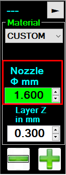
1. On the head, we use the number you have for nozzle diameter to make our flow calculations. See Flow Rate for details about how we determine how fast to spin the motor so that you get the proper volume per second of deposition. This image is for printing with a 14# (fourteen gauge, or 1.6mm ID) luer needle:
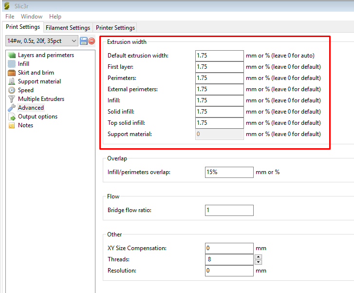
2. In the recipe, we use the extrusion width numbers to determine how far apart to place each bead of material. We expect your extrusion width to be 10% wider than your nozzle diameter (to allow for a nice sandbag-shaped cross section). This image is for printing with a 14# (fourteen gauge, or 1.6mm ID) luer needle:
This applies to everything we print, from PLA to Porcelain to PEEK.
Please note that we do NOT use any other variable relating to nozzle diameter. Not Bridge Flow Ratio. Not Nozzle Diameter. Not Extrusion Multiplier. All of these variables affect the E values in your gcode. Which we then ignore.
How do I convert DXF files to gcode?
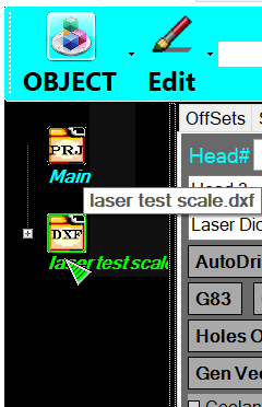
1. In Project Composer, open your DXF:
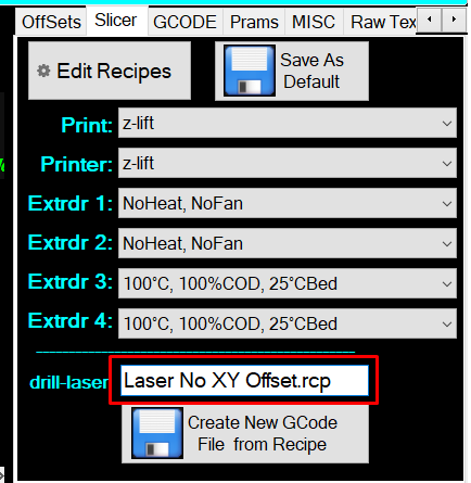
2. On the Slicer tab, double click in the text box next to drill-laser, and select the recipe:
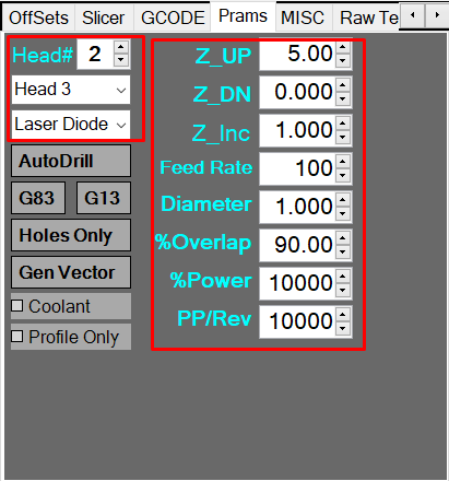
3. On the Prams tab, configure the head and settings to use:
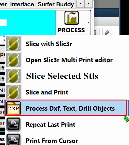
4. Process > Process DXF, Text, Drill Objects:
5. Profit!
I get errors on v4!
So, if your gcode is just for one head, which isn't specified, and you only have one head loaded, Repetrel always has and will still print with that head.
Missing Tx Argument
However, not coding the tool to be used is unacceptable in the CNC world, and we want people to get used to coding in their tool assignments. And yes, it should say Tx command, not Tx argument.
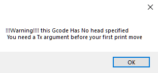
As detailed at the very top of the Gcode Page, you should use a T# command, where # is the slot of the tool you will use, starting with T0 for the left most slot, T1 for the second from the left, etc. Failure to do this will pop up this warning:
This is non-fatal; you can just hit enter or click "OK" and continue, but we want to encourage you to specify which tool to use.
Heads Not Installed
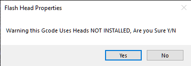
So, you've bypassed (or didn't get) that first error, and now you get another error:
This means that when your file was loaded, it was scanned for any Tx commands - but when you pressed print, the tool positions occupied on the printer don't match the tool assignments in the gcode. Again, this is non-fatal, and if you know your setup is correct, you can hit enter or click "Yes". But, again, we want you to know that the configuration detected on the printer does not match the configuration specified in the gcode.
But It Matches!
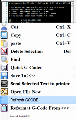
So, perhaps you've gotten these errors, and then edited your gcode file to specify T1, which matches the slot where your head is loaded. Well, we don't scan the gcode a second time 'unless your right-click in the gcode and select "refresh gcode"' - doing this will eliminate getting this message after you have edited in the assignment:
How do I know which T parameter to use?
Awesome question. We know it can be confusing, and that's why we have pages explaining just that!
For Repetrel version 4 and earlier, please see T v4.
For Repetrel version 5 and later, please see T v5, where we've simplified this!
Why do you put a full computer in every printer?
We decided to include the embedded PC in our printers because it enables us to:
1. Provide online support in real time; and
2. Expand the printer’s capability in the future.
There is NO question that this is valuable. Every time we walk a customer through a new procedure, or help diagnose what is going on with their printer via Team Viewer, we are absolutely sure that having the embedded PC was one of the best ideas we have had.
Some people see our printer and really like the hardware, but of course the price is not cheap, because the components are world class quality. These people may find it hard to afford to purchase a printer with an embedded PC, but the PC and touchscreen add a mere $350 to the actual cost of the printer (we make NO profit from the PC; we offer it because it makes the printer that much better, and easier to grow with).
For them we offer a Printer without a PC; however, we strongly suggest that this ONLY be done by people that are VERY computer literate. We factored in 5 hours of personal training on each printer, because this is a new technology and we found that everyone really benefited from this training. We did NOT factor in any time to help people that were trying to get modern software running on an old PC from the garage and save $350 on their printer, because our time is valuable and an old PC is a complete unknown.
The embedded PC comes configured and tested. This is by far the best way to get a great 3D printing experience.
We have always tried to operate with the mindset of: we treat the customer the way we want to be treated. We would much rather spend our time helping someone learn how to print than spend it trying to debug some unique and unknown computer installation.
How do I create or import the files for the part I want to print?
You can create your stl file with most of the popular cad packages, such as SolidWorks, AutoCad, Alibre, FreeCad, Google SketchUp, ProE, TurboCad, etc.
We bring the .stl file into MeshLab to heal the file (remove reference lines, resolve duplicate vertices, etc.).
Then we bring the healed .stl file into Slic3r to slice it (convert it into the G-code that drives the printer). We will provide typical Slic3r recipes (temperature, flow rate, movement speed, layer thickness, etc.) for filaments and extrudables.
Then we use our very customized version of Repitier Host, which drives the printer to create your part using the G-code from Slic3r.
Why does my motor grind on the filament?
Standard causes and solutions for the motor grinding on the filament (and not advancing it as rapidly as needed):
| Possible Cause | Suggested Fix |
|---|---|
| Friction or resistance on the delivery path before the motor shaft, including things like: | |
| tangled spool kinked filament sharp entrance angle where filament enters guide tubing kinked tubing. |
untangle unkink make gentler angle unkink |
| Friction or resistance on the exit path after the motor shaft, including things like: | |
| Filament not fully melting fast enough for the demanded throughput. Nozzle too narrow for the demanded throughput. Nozzle too close to build surface, causing back pressure. |
Try higher temperature, thinner layers, and/or slower print speed. Try extra torque head, or suggestions above. Reestablish Z-zero positioning. |
| Buildup on drive shaft hobs (teeth). | Use vacuum or air pressure to clean out the hobs for optimal filament engagement and drive. |
What Maintenance Should I Do?
The majority of our motion bearings come from PMI, and here are their recommendations: http://www.pmi-amt.com/en/products/amt_options.htm
You can use a grease or an appropriate liquid oil. You can buy the manufacturer's oil applicator, but other machine oils such as "sewing machine oil" should be fine.
Oil is definitely the simplest. Just spread a few drops on the rail after wiping off all debris.
Other than cleanliness (and a low-humidity environment), no other maintenance is required unless some problem arises.
How do I slice for 4th- or 4th-and-5th-axis machining?
We normally do it by hand, but we also recommend SimplyCAD, which his free.
Why doesn't one tool position work?
If you have one slote (or more) in which no heads heat up or advance material, but these heads work on other slots, you've probably blown one fuse (or more). These are easy to replace:
You'll need to ensure that this is the problem:
- Power down.
- Remove the silver Phillips screws so that you can lift the upper yoke board up and pull it back, out of the way.
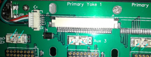
- Check for resistance from one side of each fuse to the other (see blue arrows). Any fuse with 0 Ohms is good, but anything greater is blown.
New Style
From around 2016 on, we've been using fuse holders, which allow easy replacement:
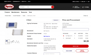
These can be reordered from Digi-Key, or directly through us.
Old Style
Units from before 2016 may have fuses soldered in place:
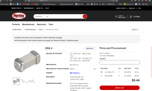
These can be reordered from 4/507-1084-1-ND/615045 Digi-Key, or directly through us.
Replace the Fuse
Replace the old, blown fuse with a new one (you may opt for a larger fuse, but only 15 amps maximum is sent to the yoke) by either simply swapping them out (new ones) or using a soldering iron to remove the old and attach the new (older ones).
Power up and test!
What's that Clicking?
When you hear clicking from a filament head, and material isn't coming out properly, it means that the head cannot advance the material as fast as the gcode demands. Possible causes and solutions:
Mechanical or Logical?
Question: Is this a problem with throughput in general, or with this print in particular?
Investigation: Position the head above the bed (in mid air) and at print temp (240°C for ABS, 210°C for PLA, etc.); attempt to manually advance material at 500 pulses/second (500 on the screen).
Answer 1: If this does not work, you have some mechanical issue - go to Case 1: Mechanical.
Answer 2: If this works, your head is functioning normally, but we'll need to adjust your parameters - go to Case 2: Logical.
Answer 3: If you cannot bring the head to the proper temperature for printing, we have a heating issue - go to Case 3: Heating.
Case 1: Mechanical
Most Common Cause: Input Problems.
Most Common Solution: Find and remove cause of input restriction. Please ensure that there is smooth, low-friction delivery from the spool, through the pneumatic fitting on the chassis, through the PTFE tubing, through the pneumatic fitting on the head, and into the Feed Chamber on the head. There should be no bends or kinks or sharp angles, and no dragging across sharp surfaces. Filament should inter interior PTFE shaft after passing the drive shaft, centered on the hobs (gearing) and pressed firmly (but not too tightly) by two bearings separated by a washer. If you've disassembled and reassembled this part, ensure that this bearing rod is not flipped.
Less Common Cause: Output Problems.
Less Common Solution: Find and remove the cause of the output restriction. While rare (we do test prints with every head and every printer before shipping them), it's possible that some foreign material made its way into the fusion chamber or melting zone of the nozzle. Please follow instructions above for changing and cleaning nozzles, but replace the same nozzle.
Case 2: Logical
Most Common Cause: Temperature is too low for this combination of Material, Layer Thickness, and/or Print Speed.
Resolution: Use a higher temperature and/or thinner layers and/or slower print speeds.
Less Common Cause: If on first layer, perhaps Z-zero is wrong and nozzle is too close to build surface.
Resolution: Ensure bed is level; recalibrate Z-zero.
Case 3: Heating
If the head is not reaching temperature, or not maintaining temperature, we need to find out why:
Is the head set to the right temperature? Just look at the GUI to tell. If it cannot be set to the right temperature, some settings are wrong. Please contact me, hyrel3d@gmail.com or 404-914-1748.
Does the head reach the right temperature? Again, check the GUI. If the head is set properly, but does not warm up, we'll need to check to see if it's getting 12VDC. Please contact me, hyrel3d@gmail.com or 404-914-1748.
Does the head stay at the right temperature? Right, GUI again. If the head is set to temp, but later becomes set to a lower temp (or turned off), I'll need to examine your settings and gcode. Please contact me, hyrel3d@gmail.com or 404-914-1748.
What's the Reset Button?
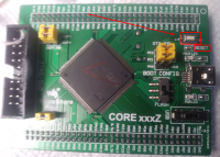
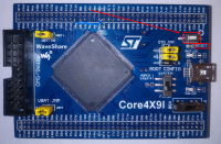
The Reset button will clear and reestablish communications between the motion controller (the STM407 on the ESR and 30M, or the STM429 on the EHR and Hydra). This doesn't necessarily happen with a reboot, so sometimes we want to be sure it happens; but it's not a panic button, and you shouldn't press it if you don't need to. It's a small button on the motion controller, but we configure another button as well.
The internal button looks like this on the 407 (ESR, 30M):
The internal button looks like this on the 429 (EHR, Hydra):
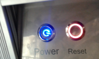
The external button on the 30M is on the front panel, and looks like this:
The external button on the ESR and EHR is on the right side and looks like this, although it used to be a green or red button:
The remote button on the 16A is located inside, behind the control panel, and looks like this:
