Difference between revisions of "Repetrel"
| Line 285: | Line 285: | ||
[[File:Headdata mk1-250.png]] | [[File:Headdata mk1-250.png]] | ||
* The numbers shown in blue represent the current temperature in degrees Celsius. If this shows XXX or a very unrealistic temperature, it means your head either has no RTD (thermal reading device), or is set as the wrong type of RTD. The temperature also acts as a "first" (2.855 and earlier) or "previous" (newer versions) page button, depending on the release. | * The numbers shown in blue represent the current temperature in degrees Celsius. If this shows XXX or a very unrealistic temperature, it means your head either has no RTD (thermal reading device), or is set as the wrong type of RTD. The temperature also acts as a "first" (2.855 and earlier) or "previous" (newer versions) page button, depending on the release. | ||
*To the right of the temperature is a right-arrow, which will allow you to page through the data on the head. | *To the right of the temperature is a right-arrow, which will allow you to page through the data on the head. | ||
*'''MK1''' is the first page displayed on a head flashed as an MK1-250. | |||
**The first box is the '''Temperature''' box, which when not engaged, will show as green, displaying 0 degrees with an "OFF" icon; and when engaged will show as yellow, displaying the default temperature with an "ON" icon. | **The first box is the '''Temperature''' box, which when not engaged, will show as green, displaying 0 degrees with an "OFF" icon; and when engaged will show as yellow, displaying the default temperature with an "ON" icon. | ||
**The second box is the '''RUN''' box, which, when not engaged, will show as green, displaying the word "RUN" and a grey motor icon; and when engaged will show as yellow, displaying the default manual speed (typically 500 pulses per second), and arrows on the motor icon. | **The second box is the '''RUN''' box, which, when not engaged, will show as green, displaying the word "RUN" and a grey motor icon; and when engaged will show as yellow, displaying the default manual speed (typically 500 pulses per second), and arrows on the motor icon. | ||
**The third box is the '''FAN''' (or, on some heads, crosslink) box, which when not engaged will show as green, displaying the word "OFF" and a fan icon; and when engaged will show as yellow, displaying the duty cycle of the fan (or LEDs), and a circle around the fan blades. | **The third box is the '''FAN''' (or, on some heads, crosslink) box, which when not engaged will show as green, displaying the word "OFF" and a fan icon; and when engaged will show as yellow, displaying the duty cycle of the fan (or LEDs), and a circle around the fan blades. | ||
*'''Material''' is the second page dipslayed. | |||
**The first item will show "ABS>235" or some other setting (including "CUSTOM"), indicating the ''Default Material''' and temperature selected. | |||
**The second item will show what '''Color''' the temperature plot will render for this head. | |||
**The third item will display the presently set '''Nozzle Diameter''' for the head. ''''It is critical for proper flow calculations that this number is accurate.'''' | |||
**The fourth item will display the default '''Layer Thickness''' in mm. This will later be overwritten by gcode. | |||
*'''Temp Info''' is the next page. | |||
**'''Print Temp''' shows the default temperature to which the head will be set, should you manually turn it on. On print jobs, this should be overwritten by gcode. | |||
**'''PwrFactor''' should normally be set to 100 percent. | |||
**'''MIN''' and '''MAX''' should list the safe operating range of the head as programmed. | |||
===== Temp Plot ===== | ===== Temp Plot ===== | ||
Revision as of 17:27, 22 August 2016
This page describes and explains the Repetrel software. To download and install the software, please see the [downloads page].
Repetrel is the name of our proprietary software which runs our equipment. It is based on an older, publicly available version of Repetier Host.
Versions
Repetrel version 2.855 was released in August, 2015, and is available [here].
Repetrel version 2.482 was released in July, 2015.
Repetrel version 1.85 was released in September, 2014.
Repetrel version 1.6 was released in July, 2014.
Repetrel version A33 was released in 2013.
Interface
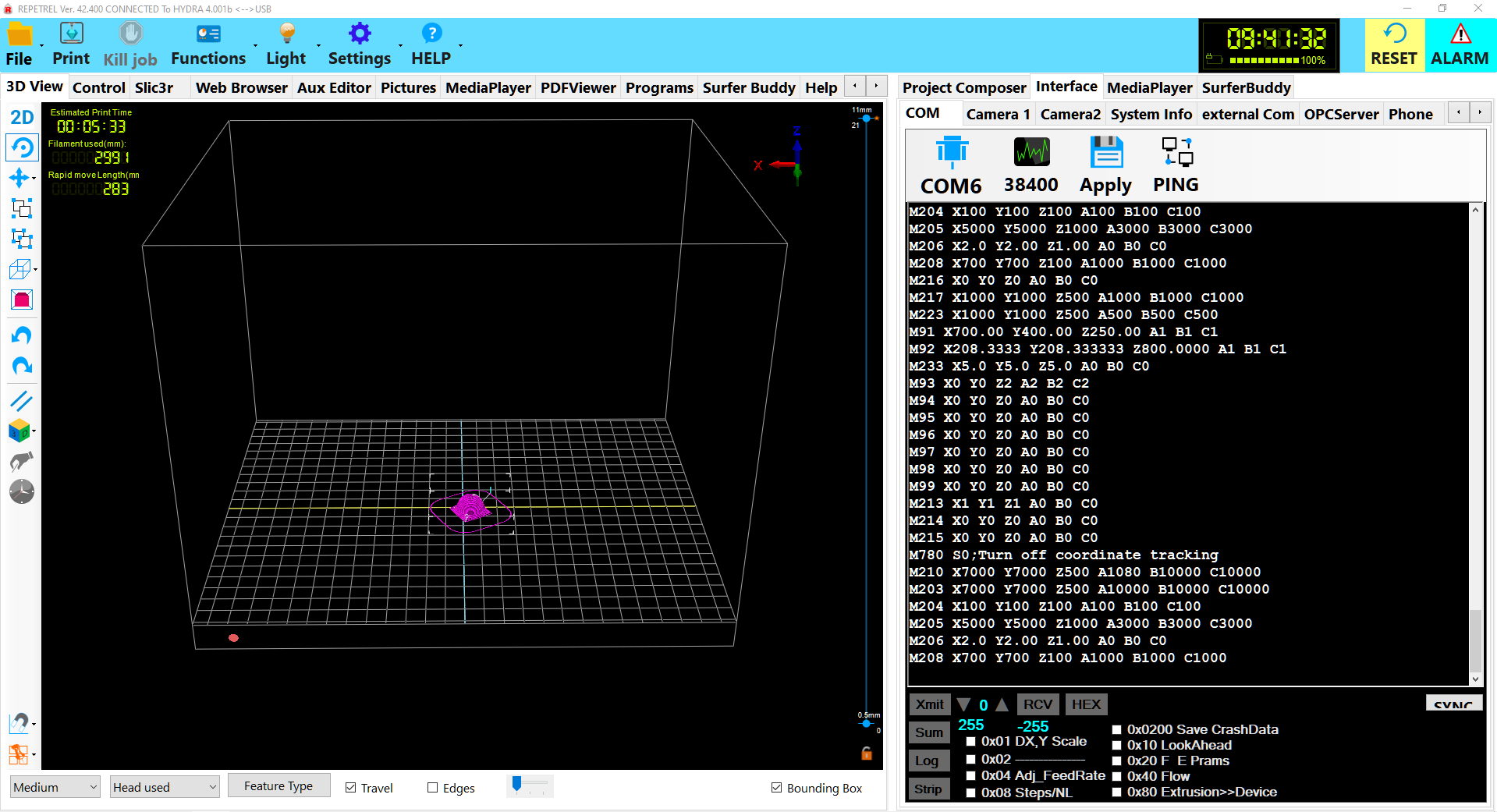
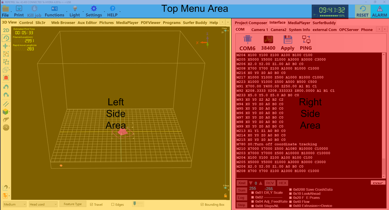
The Repetrel interface is divided into three main sections: the Top Menu Area, the Left Side Area, and the Right Side Area:
These are explained in detail in the subsequent sections:
Top Menu Area
The content of the Top Menu Area is constant and always visible, and has the following buttons/menus:
File
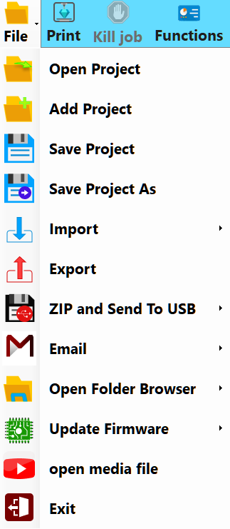
The File menu (shown to the right) has the following options:
- Open Project will open a HyProj (Hyrel Project) on a blank build area, including multiple elements as scaled/rotated/positioned.
- Add Project will add another HyProj to the current build area.
- Save Project will save all elements as displayed as a HyProj.
- Save Project As will save the HyProj as displayed with a name and location of your choosing.
- Save As has the following submenu options:
- STL will save your currently selected STL file with a name and location of your choosing.
- GCODE will save your currently selected GCODE file with a name and location of your choosing.
- Job will save your...
- Import has the following submenu options:
- Slic3r has the following submenu options:
- All Recipes will import All of our Slic3r recipes into their default locations, overwriting anything with the same names.
- All Print Recipes will import our Print recipes into their default locations, overwriting anything with the same names.
- All Printer Recipes will import our Printer recipes into their default locations, overwriting anything with the same names.
- All Filament Recipes will import our Filament recipes into their default locations, overwriting anything with the same names.
- STEP IGES FILE will allow you to designate a single STEP or IGES file to be loaded to be processed to generate GCODE.
- FLATCAM FILE will allow you to designate a single Flatcam file to be loaded to be processed to generate GCODE.
- Slic3r has the following submenu options:
- Export will...
- Zip and Send To USB has the following submenu options:
- REPETREL will...
- SLIC3R will...
- Slic3r Recipes will...
- Screen Shot will...
- Project with Source Files will...
- Screen Shot To Project Folder will...
- Project GCODE will...
- Email has the following submenu options:
- Slic3r Settings will...
- Project will...
- Contact Manager will...
- Screen Shot will ...
- Open Folder Browser has the following submenu options:
- Last Part GCODE Folder will open the directory from which the last GCODE file was opened.
- Last Part STL Folder will open the directory from which the last STL file was opened.
- Repetrel/Bin will open the C:\repetrel\bin directory.
- Default Network Location will open your default network location.
- Slic3r Recipes has the following submenu options:
- Print Recipes will open C:\Users\Hyrel\AppData\Roaming\Slic3r\print.
- Printer Recipes will open C:\Users\Hyrel\AppData\Roaming\Slic3r\printer.
- Filament Recipes will open C:\Users\Hyrel\AppData\Roaming\Slic3r\filament.
- Update Firmware has the following submenu options:
- HotHead Controller will launch the application to flash new firmware on your 103 hothead/hotbed controllers.
- 407 Motion Controller will launch the application to flash new firmware on your 407 motion controller.
- Exit will close and exit the Repetrel program.
The Print button will cause the printer to commence executing the first GCODE file in your tree view.
Kill job
The Kill job button will cause the printer to cancel the GCODE currently running.
Functions
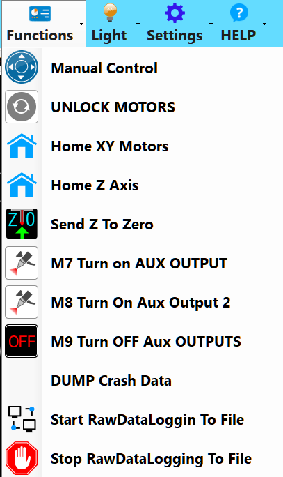
The Functions menu (shown to the right) has the following options:
- Manual Control will bring the Control Tab to the foreground of the Left Side Area.
- UNLOCK MOTORS will disengage (unlock) the motors controlling X, Y and Z positioning, allowing for manual movement.
- Home XY Motors will send the following commands:
- G28 X0 Y0 - this sends the X and Y to the home position;
- G92 X0 Y0 - this resets the home location to the current position; and
- G0 X0 Y0 - this tells the X and Y to move to the home position (where they already are).
- Home Z Axis does nothing at present.
- Send Z to Zero will send a G0 Z0 command, sending the bed and/or yoke in the Z axis to the programmed Z position.
- M7 Turn on AUX OUTPUT will send an immediate M7 command to energize the Aux Output 1 connection.
- M8 Turn On Aux Output 2 will send an immediate M8 command to energize the Aux Output 2 connection.
- M9 Turn OFF Aux OUTPUTS will send an immediate M9 command to de-energize both Aux Output connections.
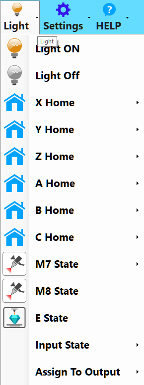
Light
The Light menu (shown to the right) has the following options:
- Turn Light On will send two commands:
- M672 S0, disabling any sensor=based triggering (see below), and then
- M670 S100 command, turning on the X-Arm light.
- Turn Light Off will send an M670 S0 command, turning off the X-Arm light.
- X Axis Home Sensor will send an M672 S1 command, so the X-Arm light toggles when the X Home sensor is tripped.
- Y Axis Home Sensor will send an M672 S2 command, so the X-Arm light toggles when the Y Home sensor is tripped.
- Z Axis Home Sensor will send an M672 S3 command, so the X-Arm light toggles when the Z Home sensor is tripped.
- W Axis Home Sensor will send an M672 S4 command, so the X-Arm light toggles when the W Home sensor is tripped. As of August, 2016, there is NO W Axis or W Axis sensor on any production model.
- X Axis Stall Sensor will send an M672 S5 command, so the X-Arm light toggles when the X Stall sensor is tripped.
- Y Axis Stall Sensor will send an M672 S6 command, so the X-Arm light toggles when the X Stall sensor is tripped.
- Z Axis Stall Sensor will send an M672 S7 command, so the X-Arm light toggles when the X Stall sensor is tripped.
- W Axis Stall Sensor will send an M672 S8 command, so the X-Arm light toggles when the X Stall sensor is tripped. As of August, 2016, there is NO W Axis or W Axis sensor on any production model.
- M7 Output Status will...
- Turn Off Scanner Grid Light will send an immediate M671 S0, which does nothing at present.
- Turn On Scanner Grid Light will send an immediate M671 S255, which does nothing at present.
- Run Scan Motor does nothing at present.
- Stop Scan Motor does nothing at present.
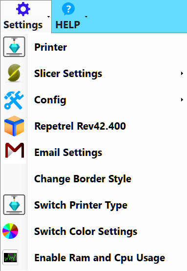
Settings
The Settings menu (shown to the right) has the following options:
- Printer will launch the Printer Settings configuration tool, which has three tabs:
- The Printer tab allows for configuration of G0 Rapid Movement Rates, Park parameters, Home Parameters, and Actions after Job Kill.
- The Printer Shape tab allows for configuration of Print Area, Travel Limits, Dump Area, and Custom Pulses per Millimeter settings in each axis. Most users should NEVER change these settings.
- The Advanced tab has options for post-slicing filters.
- Slicer Settings will actually launch the Slic3r homepage in the Web Browser tab.
- Config has the following options:
- Language has options for various languages.
- Set Working Bin Directory will allow you to select a different working directory. Use with caution.
- Repetrel general configuration allows for a few configuration changes.
- Sound Configuration allows for audio notifications of certain events.
- FTP allows for storage of a default FTP credentials.
- Repetrel displays the version of Repetrel which you are currently using. The Repetrel Updates option is not presently working.
- Email Settings allows for storage of a default email credentials.
- Change Border Style toggles display of a window border, allowing for resizing and repositioning. Note that with the border displayed, some portions of the Repetrel interface may not be displayed.
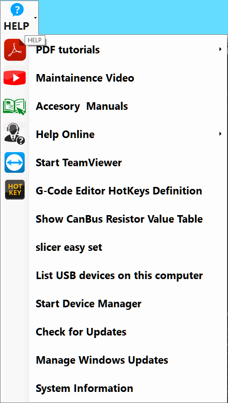
Help
The HELP menu (shown to the right) has the following options:
- PDF tutorials has the following options:
- 1. Hyrel_Quickstart gives a quick overview of unpacking, setting up, and printing.
- 2. Hyrel_Intro_EMO gives a review of the first training session, including printing with the EMO-25.
- 3. Hyrel_MK1_Single gives a review of the second training session, including printing with the MK1-250.
- 4. Hyrel_MK1_Multiple gives a review of the advanced training session, including parallel (clone) and series (cooperative) printing with multiple heads.
- Video Tutorials does nothing at present.
- Maintenance Video does nothing at present.
- Accessory Manuals has the following options:
- Drill Mill Head Manual explains the ST1 Spindle Tool.
- EMO 25 Manual explains the EMO-25 print head.
- HotHead Controller Schematic - 102081_1 explains the 103 Controller Board.
- HotHead SDK explains the Software Developer's Kit for print heads.
- MK1 250 Manual explains the MK1-250 print head.
- Shark V Laser Manual explains the modular laser heads.
Power Indicator, Clock
The Power Indicator shows battery charge / AC power. The Clock shows the current time.
ALARM
The ALARM button will actually force Repetrel to the background, enabling viewing of other windows.
RESET
The RESET button will initiate a soft reset of the 407 Motion Controller.
Left Side Area
The content of the Left Side Area is dynamic, changing depending on which of the Left Side Tabs you have selected:
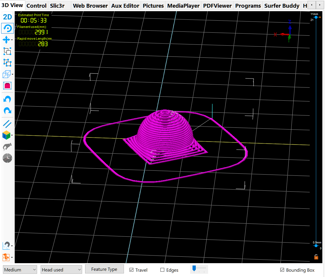
3D View
The 3D View tab (shown to the right) displays a rendering of the build area above a log of selected messages. The icons to the right allow one to:
- Rotate the view
- Move Viewpoint (or pan) the view
- Move Camera on the view
- Move Object (or drag the object)
- Zoom the view
- Change 'Orientation of the view to:
- ORTHO View - looking from the front and above
- TOP View - looking from above, centered
- Front View - looking from the front, centered
- Back View - looking from the back, centered
- Side View - should be looking from the side; as of 8/22/2016, looking from the top, centered.
- Bottom View - looking from the bottom, centered
- Use Parallel Projection
- CSG has options for:
- Merge - this will combine two STL files into a single STL as positioned.
- Subtract - this will evacuate the area of one STL from another as positioned.
- Intersection - this will generate a new STL where two others intersect as positioned.
- Mirror - no apparent function as of 8/22/2016
- Grid Snap has options to lock your STL dragging to discrete increments:
- Grid Snap OFF
- Grid Snap 1.0mm
- Grid Snap 5mm
- Grid Snap 10mm
- Grid Snap 25mm
- Visualization Settings has options to configure your visualization:
- Show Print Bed
- Set Print Bed Color
- Set Background Color
- Set Selected Object Color
- Copy Image to Clipboard
Beneath the 3D View main window is a text window, where certain events are displayed. Right-clicking on this text window provides the following options:
- Copy
- Paste
- Cut
- Clear All Text
- Show/Hide ToolBar
- Show/Hide Event Log Settings Box, which will allow you to specify where and in what format log files are spooled. Double-clicking in the settings area returns the standard text window.
- Save Highlighted Text to File
- Save to default File... (location/name)
- Start File Stream to... (location/name)
- Stop File Stream to... (location/name)
- Apply Settings As Power On Default
- MoveTextToBuffer
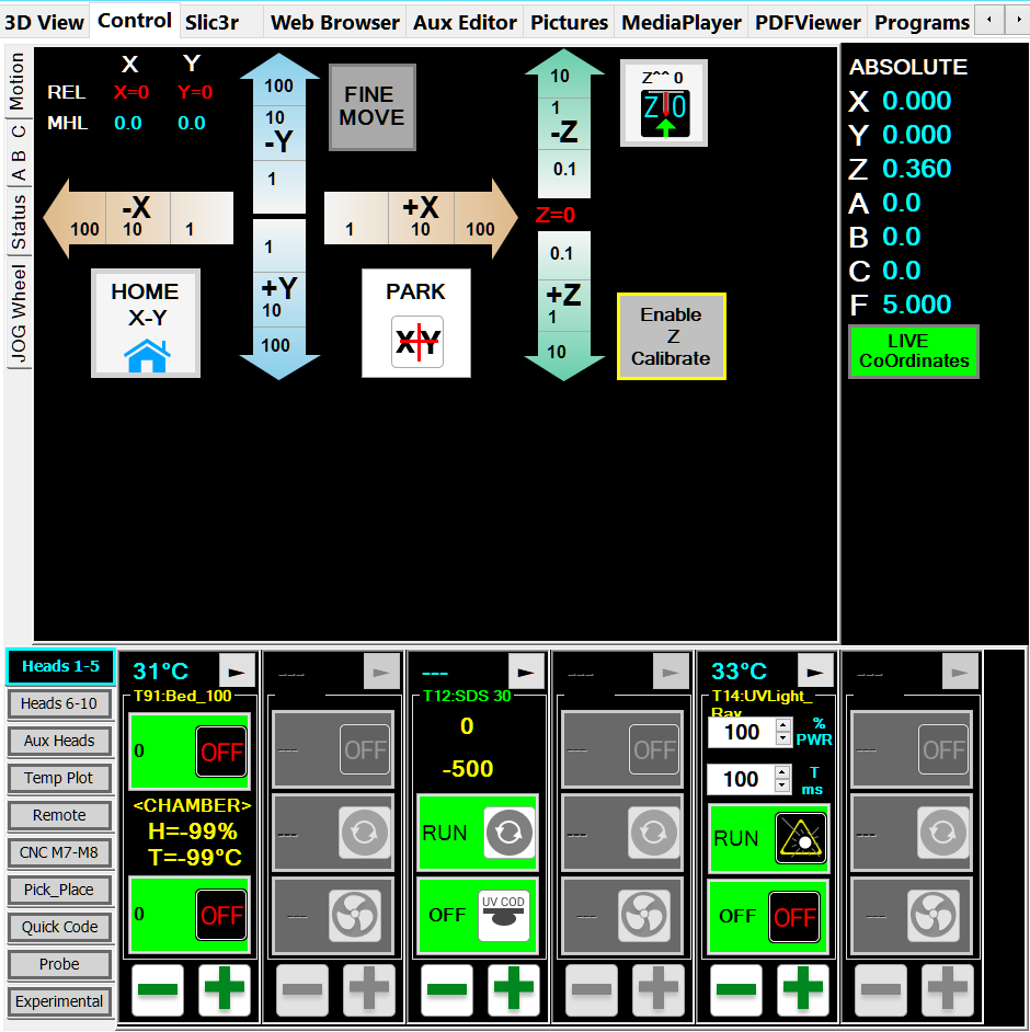
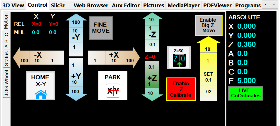
Control
The Control (formerly Manual Control) tab (shown to the right) has Top and Bottom halves; each half has multiple side tabs. The first tab displayed, the Manual tab (Top) and the Head CTRL tab (Bottom) are the primary tabs. The other Top Tabs (Advanced, Table, and Debug) are only used in testing at present. The other Bottom tab (Temp Plot) is used by some users.
Motion
The Motion side tab, in the top portion of the Control tab, deals with manually directing the X/Y/Z motion of the printer, and manually setting the Z-Zero position.
- The Positioning Data will display the current relative and absolute positioning. This is used when calibrating the head offsets.
- The Tan X arrows will move the bed by the displayed distance, in the displayed direction.
- The Blue Y arrows will move the yoke by the displayed distance, in the displayed direction.
- The Green Z arrows will move the bed by the displayed distance, in the displayed direction. Note, this will not be allowed to exceed the user-set (or default) Z-Zero setting. See the Z Calibrate entry, below.
- The Home X-Y button will send the yoke and bed to the home positions.
- The Park XY button will send the yoke and bed to your preconfigured Park location. Note, this merely adds a set amount to your current location, and the unit should always be homed (Home X-Y) before being Parked.
- The Fine Move button will change the X/Y/Z arrows to use smaller distances for fine tuning offsets.
- The Z^^0 button will send the bed up to the user-set (or default) Z-Zero setting. See the Z Calibrate entry, below.
- The Enable Z Calibrate button will enable the Yellow SET Z arrow, below. This should only be enabled when actually setting the Z-Zero.
- The Yellow SET Z arrow will allow the bed to move up past the current Z-Zero position, AND it will set a new Z-Zero position at the Z location to which you move the bed.
Advanced
The Advanced tab has some test and experimental settings, and should not be used.
Table
The Table tab has some legacy information which is now properly viewed on each head, and should not be used. See #Head_CTRL
Debug
The Debug tab has some test and experimental settings we use during production, and should not be used.
Head CTRL
The Head CTRL side tab, in the bottom portion of the Control tab, deals with manually setting or changing the data on the modular heads. These shots are taken from the display of an MK1-250 head:
- The numbers shown in blue represent the current temperature in degrees Celsius. If this shows XXX or a very unrealistic temperature, it means your head either has no RTD (thermal reading device), or is set as the wrong type of RTD. The temperature also acts as a "first" (2.855 and earlier) or "previous" (newer versions) page button, depending on the release.
- To the right of the temperature is a right-arrow, which will allow you to page through the data on the head.
- MK1 is the first page displayed on a head flashed as an MK1-250.
- The first box is the Temperature box, which when not engaged, will show as green, displaying 0 degrees with an "OFF" icon; and when engaged will show as yellow, displaying the default temperature with an "ON" icon.
- The second box is the RUN box, which, when not engaged, will show as green, displaying the word "RUN" and a grey motor icon; and when engaged will show as yellow, displaying the default manual speed (typically 500 pulses per second), and arrows on the motor icon.
- The third box is the FAN (or, on some heads, crosslink) box, which when not engaged will show as green, displaying the word "OFF" and a fan icon; and when engaged will show as yellow, displaying the duty cycle of the fan (or LEDs), and a circle around the fan blades.
- Material is the second page dipslayed.
- The first item will show "ABS>235" or some other setting (including "CUSTOM"), indicating the Default Material' and temperature selected.
- The second item will show what Color the temperature plot will render for this head.
- The third item will display the presently set Nozzle Diameter for the head. 'It is critical for proper flow calculations that this number is accurate.'
- The fourth item will display the default Layer Thickness in mm. This will later be overwritten by gcode.
- Temp Info is the next page.
- Print Temp shows the default temperature to which the head will be set, should you manually turn it on. On print jobs, this should be overwritten by gcode.
- PwrFactor should normally be set to 100 percent.
- MIN and MAX should list the safe operating range of the head as programmed.
Temp Plot
The Temp Plot side tab, in the bottom portion of the Control tab, allows users to view heating and cooling data.
Pictures
asdf
Web Browser
asdf
Aux Editor
asdf
Help
asdf
Slic3r
asdf
Programs
asdf
Right Side Area
The content of the Right Side Area is dynamic, changing depending on which of the Right Side Tabs you have selected:
Project Composer
asdf
OffSets
Slicer
GCODE
Prams
GCODE Visual
MISC
Raw Text
Zebra Prints
Pick_Place
Fixture Helper
G54-59
FIND
VIEW
TEXT
G0-G1
Copies
HELPER
EZ Print
Comm Link
asdf
Camera
asdf
Live Video
Capture Picture
Live Canny
TabPage4
TabPage5
3DVisualSettings
asdf
