UV Array
Please use personal protective equipment and follow your facility safety guidelines at all times.
Hardware
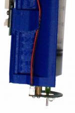
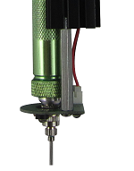
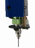
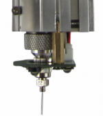
The first step is to ensure that the array is properly mounted:
If you are using an SDS head (which takes plastic syringes), we mount the array with M3 standoffs:
If you are using an EMO, VOL, KRA, KR2, or TAM head (which take aluminum or stainless reservoirs), we mount the array with M4 standoffs:
The next step is to ensure that the UV Array is connected to the material head circuit board.
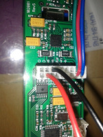
Firmly but gently grasp the 18-pin connector and pull it straight away from the circuit board. You will seat the black wire in the top row, third position (marked "Gnd" on the board), and the red wire in the bottom row, second position (marked "Aux" on the board, if you can read it). This will allow the 12VDC to power the array.
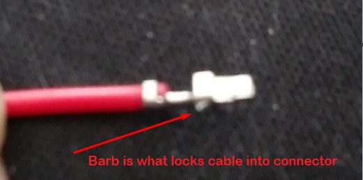
The best method to seat these crimped wires is to align the barb on the crimp up or down to point toward the plastic finger that will hold it in place. The barb is tiny, and is on the side that extends down to the wire insulation (sorry about the focus):
On your connector, since the black wire will go on the top row, the barb should be pointing up; the red wire will go on the bottom row, and the barb should be pointing down. If you pull gently on the wires, you should feel the barb catch on the plastic finger, and thee wire should remain seated in the connector.
When you seat the connector on the circuit board, it should now look like this:
If you load the head onto the printer, you should be able to toggle the COD button on the interface and control the UV Array intensity:
Depending on your wavelength, this might not be visible to the eye without using a full spectrum camera (some smartphone cameras work).
The D6 LED on the head's STM-103 circuit board should always be illuminated with the relative intensity of your M106 output, between 0 and 100 percent.
Gcode
For the proper gcode to work your array (M106) and examples, please see UV_and_Clench#Gcode
